

About This Project
In this tutorial, we will learn how to make Push Button LED Circuit on breadboard.
Project Info
- Difficulty: Easy
- Estimated Time: 30 min
- Category: Breadboard
- Tags: LED, Switch, Breadboard, Battery, Resistor, Jumper wire.
Introduction
A switch is a device used for making/breaking the connection in an electric circuit. It enables/disables the flow of current to the device so that it can be used whenever necessary. A switch can be used to turn ON/OFF a device. We are going to use a push-button for controlling the LED.
LED (light-emitting diode) is a semiconductor device that emits light when an electric current flows through it. When current passes through an LED, the electrons recombine with holes emitting light in the process. LEDs allow the current to flow in the forward direction and block the current in the reverse direction.
For more information about LED click here.
What is a Push Button?
Push Button is a switch that helps in complete the circuit when it is pressed. It is a type of switch that works on a simple mechanism called “Push-to-make”. When one leg of the push button is connected to a positive supply and the other one is connected with LED via the resistor. It is used in many circuits to trigger the system.
The push button has a spring inside that brings it back to the initial position as soon as the button is released. This button is made up of plastic or metal. It has 4 legs; two on each side. The legs on both sides are internally connected. This allows users to operate two lines of the circuit by a single push button. When the button is pressed, it conducts current through it and makes the circuit. When the button is released, it breaks the circuit.
Project: How to make a push button LED circuit.
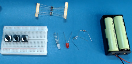
Components Required
| Image | Component | Quantity |
|---|---|---|
 |
Breadboard | 1 |
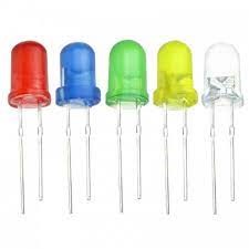 |
LED’s | 1/2 |
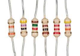 |
Resistor 220 ohm | 1/2 |
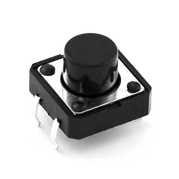 |
Switch (Push Button) | 1 |
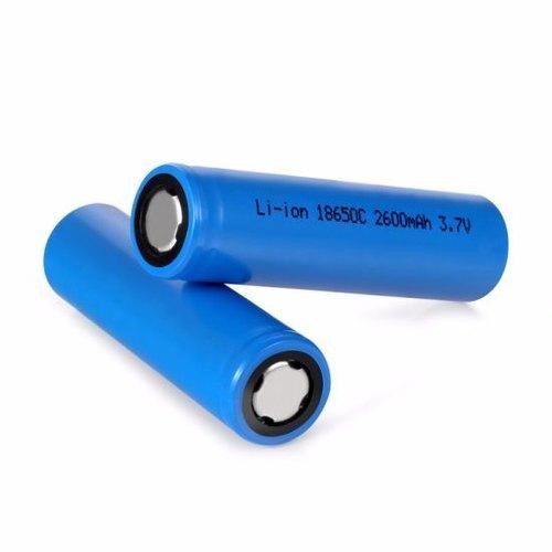 |
Battery | 2 |
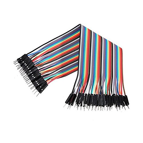 |
Jumper Wires | 5-6 |
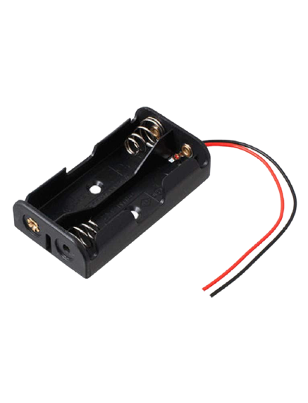 |
Battery Holder | 1 |
Building Guide
Step 1: Circuitry of the Breadboard
- Power the components
- Power the LED
- VCC to 5V
- GND / to GND
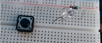
Step 2: Assembly
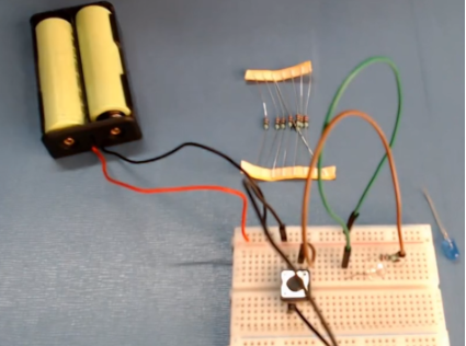
- Assemble all the components required
- Insert LED, Resistor, and switch on the breadboard as shown below.
- Connect the jumper wires.
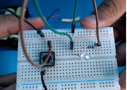
- Power up the breadboard by providing positive and negative supplies from the battery.
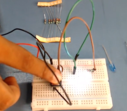
- When we press the button, the LED light glows.
With this, we have come to an of this project. Hope you liked the project. Have any question related to the project? Leave your comments below.
