

Motor Control
Many robotics and automation applications require motor control to function. It enables us to direct motor movement, which is essential for building autonomous robots. Up to four DC motors can be controlled with the commonly used motor driver IC known as the L293D. In this post, we’ll look at how to use a CPU and the L293D motor controller to control a robot’s movement.
Materials Needed
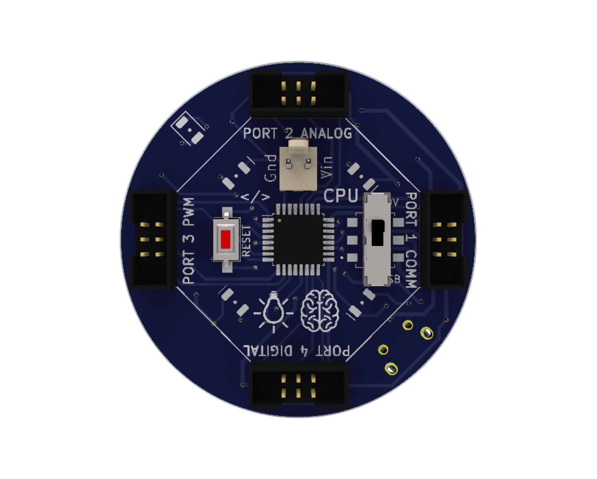
CPU: A microcontroller board that serves as the brain of the robot, which can be programmed or Bluetooth-controlled for various functions of the robot.
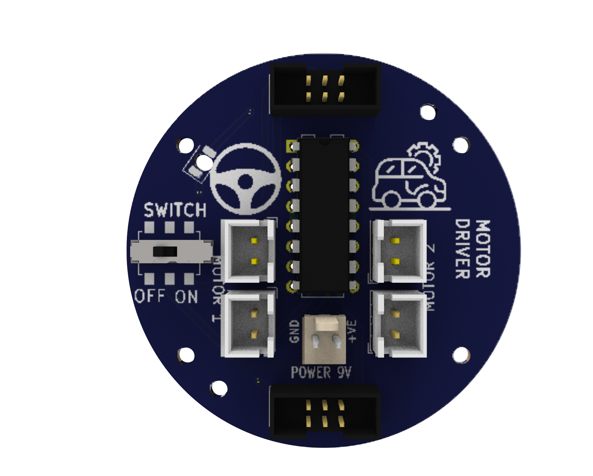
Motor Driver: A circuit that allows the robot to control the speed and direction of the motors. It provides the necessary current and voltage to the motors. We need a motor driver to drive motors because the voltage and current requirements of a motor are usually higher than what a microcontroller can handle directly. A motor driver acts as an interface between the microcontroller and the motor, allowing the microcontroller to control the motor’s speed and direction while also providing sufficient power to drive the motor. In summary, a motor driver is necessary for efficient and safe operation of a motor in a microcontroller-based system.
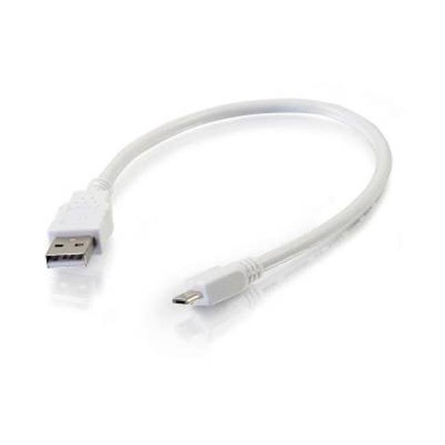
Micro USB Cable: A cable used to connect the CPU to a computer for programming or to power the CPU with a power bank.
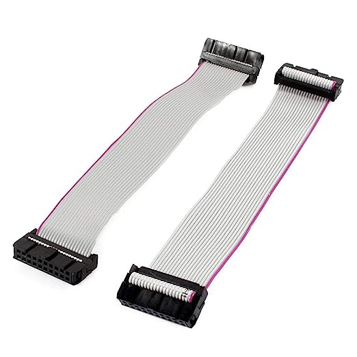
Snap Wires: Wires with pre-attached connectors that can be easily snapped on and off the components, making it easy to connect and disconnect components.
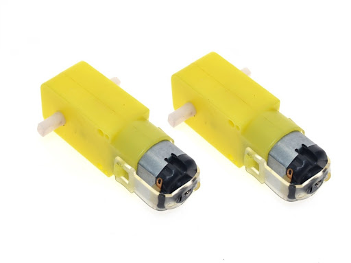
Battery-Operated (BO) Motors: DC motors with a gearbox attached to them, which allows them to provide more torque and lower speed. They are commonly used in robotics and other electronic projects.
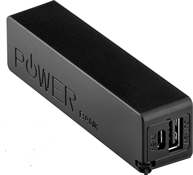
Power Bank: A portable battery pack is used to power the CPU.
9V Battery: A common battery used in electronic projects, which provides 9 Volts of power for motor driving.

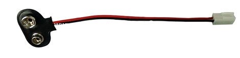
Battery to Snap Connector: A connector that allows the 9V battery to be easily connected to the motor driver.
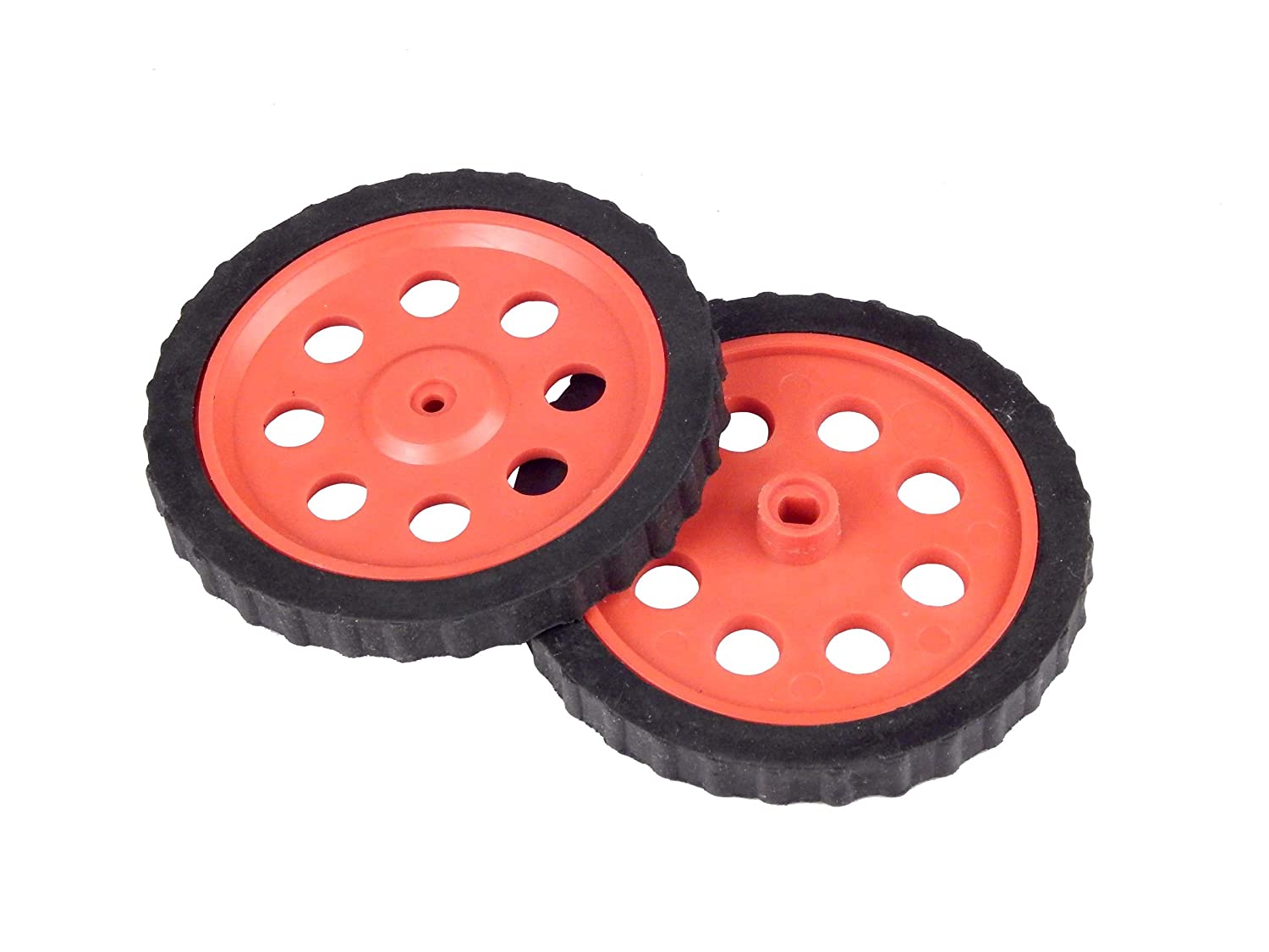
Wheels: Two wheels that drive the robot forward and backward.
Wiring the Circuit
- Connect the 9V battery to the motor driver, making sure to connect the positive and negative terminals correctly.
- Connect the two DC motors to port 1 and port 2 of the motor driver, respectively.
- Use the snap wires to make the connections from CPU port no 4 to the Motor controller.
Download Arduino IDE
You can take the following actions to download the Arduino IDE:
- Go to the official Arduino website at: www.arduino.cc
- Click on the “Software” menu item in the top navigation bar.
- Select the “Downloads” option from the drop-down menu.
- Scroll down to find the section for the Arduino IDE and select the appropriate version for your operating system (Windows, Mac, or Linux).
- Click on the download link for the selected version to start the download.
- Once the download is complete, run the installation file and follow the instructions to install the Arduino IDE on your computer.
- You can launch the Arduino IDE and begin configuring your Arduino board after installation.
Install Library in Arduino IDE
Libraries are pre-written code modules that can be used to extend the functionality of the Arduino IDE and make it easier to write code for the Arduino boards. Installing a library saves time and effort as you don’t have to write the code for the required functionality from scratch. You can simply use the pre-written code in the library and modify it according to your needs.
To install the ZIP library in the Arduino IDE, you can follow these steps:
- Download the ZIP library from a trusted source such as the official Arduino library repository or a verified third-party library repository.
- Open the Arduino IDE on your computer.
- Click on the “Sketch” menu and select “Include Library” and then “Add .ZIP Library“.
- Navigate to the location where you saved the downloaded ZIP library, select the ZIP file, and click on the “Open” button.
- Wait for the installation process to complete. You will see a notification in the Arduino IDE indicating that the library was successfully installed.
Note: Download and install the libraries given below. Ignore if already installed.
Writing the Code
We will be using the Modular library for Arduino to control the movement of the robot.
#include <modular.h>
Modular mybot;
In the setup function, we initialize the motor driver by calling the steerBotBegin function and passing the port number to which the driver is connected.
void setup() {
mybot.steerBotBegin(4);
}
In the loop function, we use different functions provided by the Modular library to control the movement of the robot. First, we call the steerBotForward function to move the robot forward, and then we add a delay of 5 seconds before moving on to the next movement.
void loop() {
mybot.steerBotForward(4);
delay(5000);
Next, we call the steerBotLeftAxial function to make the robot turn left, and then we add a delay of 800 milliseconds before moving on to the next movement.
mybot.steerBotLeftAxial(4);
delay(800);
We repeat the above steps for other movements, such as moving backward, turning right, etc. Finally, we call the haltBot function to stop the movement of the robot.
mybot.haltBot(4);
delay(2000);
Full Code for Motor Control
Testing?
- Before powering up the circuit, make sure all the connections are proper and the motor driver is connected to the appropriate motor terminals. Also, check if the power source (in this case, a 9V battery) is connected to the motor driver
- Power up the circuit by connecting the CPU to a power bank or a similar power source.
- The program consists of various motor movements such as forward, backward, left axial, and right axial movements. Observe if the motors move in the intended direction and if the timing is correct.
- If the motors do not move as intended or there are any other issues, check the wiring and the code. Make any necessary changes and retest the circuit.
- Overall, the testing conditions involve ensuring proper wiring and power connections, uploading and running the code, observing the motor movements, and making any necessary changes to the program.
Conclusion
In conclusion, using an L293D motor driver with a microcontroller such as our CPU is a great way to control motors in various applications. The motor driver allows us to drive high current motors using a low current control signal from the microcontroller, providing safety and reliability to the system. By following the proper wiring and code setup, we can control the direction and speed of our motors with ease. This project can be further extended to include other sensors and components to create a more complex and functional system.
