
About This Project
Electronic components are the building blocks of any electronic circuit, and their values must be measured to ensure that the circuit is working as expected. A multimeter is a versatile tool that can measure several electronic components’ values, including resistance, capacitance, and inductance. In this blog, we will discuss how to measure the values of electronic components with a multimeter.
Project Information
- Difficulty: Beginner
- Estimated Time: 30 minutes.
- Category: Snap Circuit
- Tags: Multimeter, Electronics, Voltmeter, Ammeter
Watch the video here.
What Is a Multimeter?
A multimeter is a versatile electronic device that can measure several electrical parameters such as voltage, current, resistance, and continuity. It is an essential tool for electrical and electronics engineers, hobbyists, and professionals who work with electronic circuits.
Multimeters come in various shapes and sizes, but they all have a few common components that enable them to measure electrical parameters accurately. These components include the display, the selection knob, the probes, and the internal circuitry.
Display: The display is the most prominent part of the multimeter and is usually an LCD or LED screen that shows the measured values. The display can show several parameters, including voltage, current, resistance, and frequency.
Selection Knob: The selection knob is used to select the desired measurement parameter. It is usually a rotary dial that is rotated to select the parameter, such as voltage or resistance. The selection knob also allows the user to select the measurement range.
Probes: The probes are the two metal leads that are connected to the multimeter. The probes are used to make electrical contact with the circuit being measured. The probes can be either detachable or fixed, and they can have various shapes, such as needles or alligator clips.
Internal Circuitry: The internal circuitry of a multimeter consists of several electronic components, including a microprocessor, an analog-to-digital converter, and various other signal conditioning components. The internal circuitry is responsible for measuring the electrical parameters accurately and displaying the values on the screen.
Types of Multimeters: There are two types of multimeters: analog and digital. Analog multimeters use a needle on a scale to indicate the measured value, while digital multimeters display the value on an LCD or LED screen. Digital multimeters are more accurate and versatile than analog multimeters and are more commonly used in modern electronic applications.
Multimeter Modes: Multimeters have various modes of operation that enable them to measure different electrical parameters accurately. These modes include:
Voltage mode: Measures the voltage in a circuit. It can measure both AC and DC voltage.
Current mode: Measures the current flowing through a circuit. It can measure both AC and DC currents.
Resistance mode: Measures the resistance of a circuit. It can measure resistance in ohms, kilohms, and megaohms.
Continuity mode: Checks if a circuit is continuous or not.
Diode mode: Measures the voltage drop across a diode to check if it is functioning correctly.
Capacitance mode: Measures the capacitance of a capacitor. 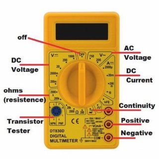
How Multimeter can help measure the values of electrical components?
This electronic device has two wires viz. black wire (which is the negative side) and the red wire (which is the positive side). These wires are inserted in the terminals on the millimeter. The knob is used to indicate the values (voltage calculation and resistance values, current flowing in the circuit). We need to rotate the knob to check the values like the continuity of wires, voltage of the battery, and value of resistors.
Measuring Resistance
Resistance is a fundamental property of any electronic component and is measured in ohms (Ω). A multimeter can measure the resistance of various components such as resistors, capacitors, and diodes.
To measure resistance, follow these steps:
- Turn off the power to the circuit.
- Select the resistance measurement mode on the multimeter. It is usually represented by the Greek letter omega (Ω).
- If measuring a resistor, remove it from the circuit.
- Touch the probes across the component whose resistance you want to measure. For a resistor, touch one probe to each lead.
- Read the resistance value from the multimeter’s display.
Measuring Capacitance
Capacitance is the ability of a component to store electrical charge and is measured in farads (F).
To measure capacitance, follow these steps:
- Turn off the power to the circuit.
- Select the capacitance measurement mode. It is usually represented by the letters “F” or “μF”.
- Touch the probes to the capacitor’s leads. The polarity of the leads does not matter.
- Read the capacitance value from the multimeter’s display.
Measuring Inductance
Inductance is the ability of a component to store energy in a magnetic field and is measured in Henries (H).
To measure inductance, follow these steps:
- Turn off the power to the circuit.
- Select the inductance measurement mode. It is usually represented by the letters “H” or “mH”.
- Touch the probes to the inductor’s leads. The polarity of the leads does not matter.
- Read the inductance value from the multimeter’s display.
Measuring Diode Voltage Drop
A diode is a component that allows current to flow in only one direction. The voltage drop across a diode is an essential parameter that determines its operating characteristics.
To measure diode voltage drop, follow these steps:
- Turn off the power to the circuit.
- Select the diode measurement mode. It is usually represented by a symbol that looks like a diode with an arrow.
- Touch the probes to the diode’s leads. The positive probe should touch the anode, and the negative probe should touch the cathode.
- Read the voltage drop value from the multimeter’s display.
Measuring Transistor Gain
A transistor is a semiconductor device that amplifies or switches electronic signals. The gain of a transistor is a measure of its ability to amplify signals.
To measure transistor gain, follow these steps:
- Turn off the power to the circuit.
- Select the transistor measurement mode. It is usually represented by a symbol that looks like a transistor.
- Connect the leads to the transistor’s base, collector, and emitter leads, as indicated by the transistor’s datasheet.
- Read the transistor gain value from the multimeter’s display.
Project: How to Measure the Values of Electronic Components with A Multimeter?
Now that we have a clear understanding of the project and the components used, let’s start the project.
Components Required
| Image | Component | Quantity |
|---|---|---|
 |
Base Grid | 1 |
 |
LED | 1 |
 |
Battery Holder | 1 |
 |
Resistor | 1 |
 |
Switch | 1 |
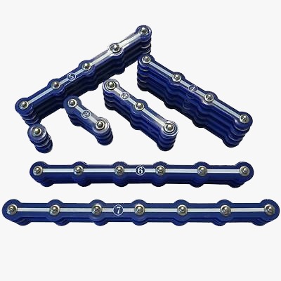 |
Snap Wires | As Per Requirement |
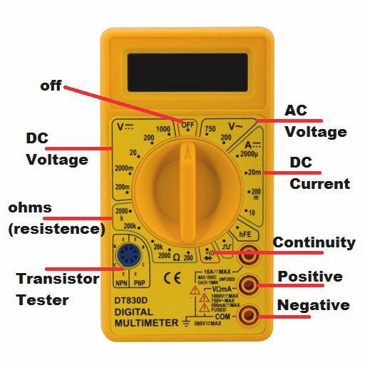 |
Multimeter | 1 |
Overview Of the Components Used
- Base Grid: The base grid works like the printed circuit boards that are found in most electronic products. It is a platform that is used to mount the parts and wires for circuit building.
- Snap Wires: The blue snap wires are the wires used to connect one component with another component. These wires are used to transport electricity. Snap wires come in different lengths so that the orderly arrangement of connections can be made on the base grid. These wires have numbers 1,2, 3, 4, and 5 on them depending on the length of the wire connection required.
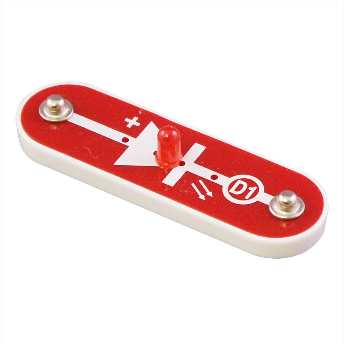
- LED: LED (light-emitting diode) is a semiconductor device that emits light when an electric current flows through it. When current passes through an LED, the electrons recombine with holes emitting light in the process. LEDs allow the current to flow in the forward direction and blocks the current in the reverse direction.
- Batteries: Only 1.5V AA type, alkaline batteries should be used for the project. You should insert batteries with the correct polarity. The batteries are non-rechargeable and should not be recharged. Check for old and new batteries, you should not mix the old and new batteries.
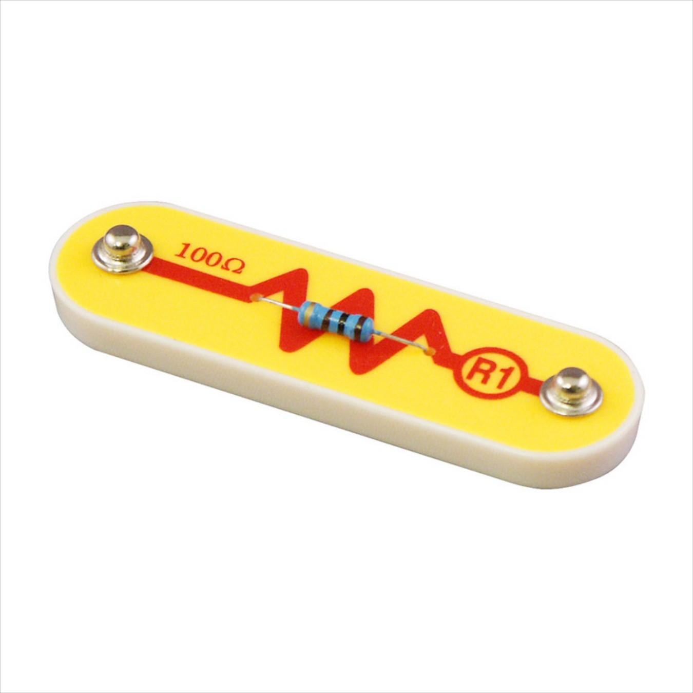
- Resistors: Resistors are used to resist the flow of electricity and control or limit the electricity in a circuit. Increasing circuit resistance reduces the flow of electricity. Resistors are used throughout electronics to limit the amount of current that flows. We have taken different resistors to check their values.
Building Guide
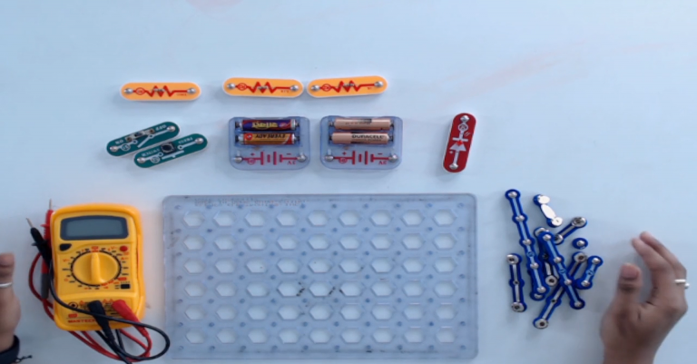
Step 1: Take out all the necessary components from the snap circuit box. We will measure the values of all the components in the kit.
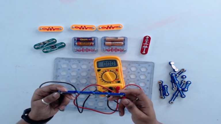
Step 2: To check the continuity of a wire, rotate its knob to the continuity position. If a wire is not broken, it will produce the beep sound. However, if it is broken, it will not produce a beep sound.
Step 3: To check the DC voltage of a battery, rotate its knob to the voltage (V) section.

- Now, connect the positive lead (red color) to the positive terminal of a battery and the negative lead (Black color) to the negative terminal of a battery.
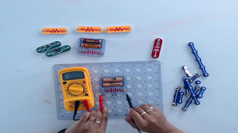
- If the value on a multimeter is showing either 1 or 0 then, change the value set on a multimeter by rotating the knob up or down.
Step 4: To check the DC current of a battery, rotate the knob of a multimeter to the current section.
- Now, connect in series with a battery and a multimeter.
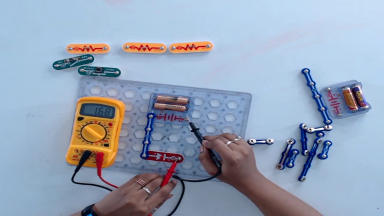
- If the value on a multimeter is showing either 1 or 0 then change the value set on a multimeter by rotating the knob clockwise or anticlockwise.
Step 5: To measure resistance, rotate its knob to the resistance(ohms) section.

- Now, connect both the terminals of a resistor with both the leads of a multimeter respectively.
- If the value on a multimeter shows either 1 or 0 then change the value set on a multimeter by rotating the knob up or down.
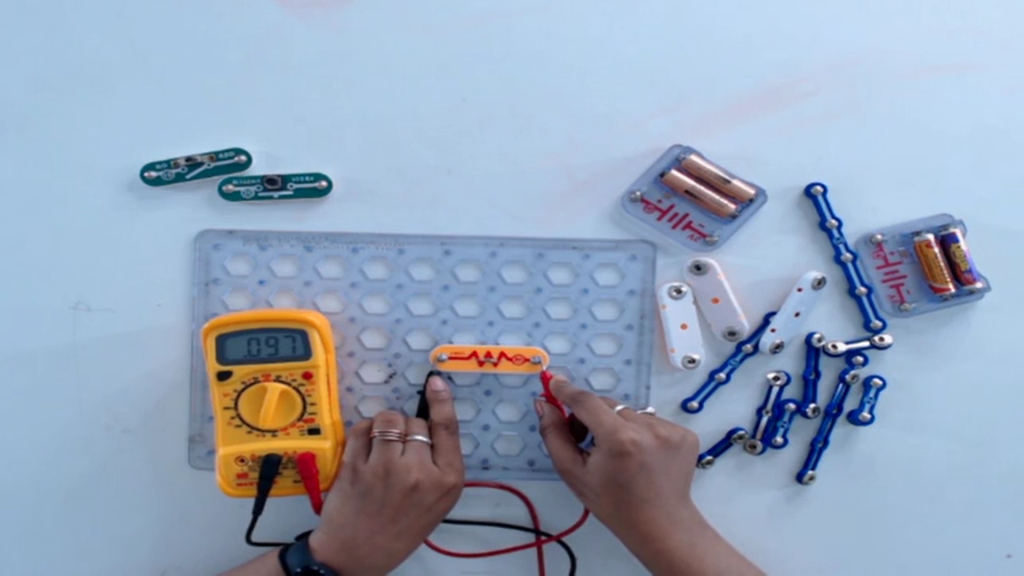
We hope you have now got a better understanding of how a multimeter works and how it helps in measuring the values of the electronic components.
Conclusion
In conclusion, a multimeter is an essential tool for any electrical or electronics engineer or hobbyist. It can accurately measure basic components such as voltage, current, and resistance, making it a versatile tool in various electrical and electronic applications. By following the steps outlined in this blog, you can effectively use your multimeter to measure these components. However, it is important to always follow safety precautions and the manufacturer’s instructions while handling electrical circuits to avoid accidents and ensure accurate measurements.


