

About This Project
In this tutorial, we will learn how to use Seven Segment Display.
Project Info
- Difficulty: Easy
- Estimated Time: 1 Hrs
- Category: Breadboard
- Tags: Seven Segment Display, Resistor, Breadboard, Battery, Jumper wire
Watch the video here.
Introduction
In many movies and TV shows. We have seen the device counts down to zero. Do you know what are those displays on which we can see the digits known as? These are Seven Segment Display (SSD), or seven-segment indicators that are electronic display devices used to display decimal numerals, etc. These are widely used as a popular way of displaying numbers.
From clocks to musical instruments and various other appliances, we get to see seven segments LED displays everywhere. They are available in many configurations. They can show time, speed, direction, capacity (of liquids), temperature, and other information that we need to monitor.
Controlling a Seven Segment Display might appear to be complex but once we understand its working, it becomes quite easy. In this tutorial, we will learn how seven segment display works. The seven segments are arranged as a rectangle of two vertical segments on each side with one horizontal segment on the top, middle, and bottom. Besides, there is a seventh segment that bisects the rectangle horizontally.
Project: what is seven segment display working and application
Now that we have a clear understanding of the project and the components used, let’s start the project.
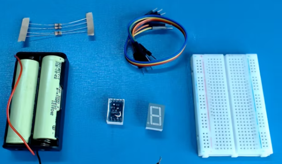
Components Required
| Image | Component | Quantity |
|---|---|---|
 |
Breadboard | 1 |
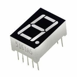 |
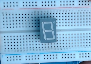
Seven Segment Display | 1/2 |
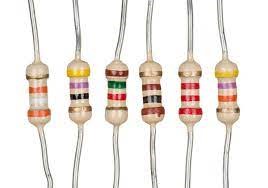 |
Resistor 220 ohm | 1 |
 |
Battery | 1 |
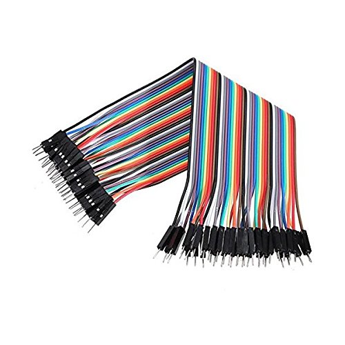 |
Jumper Wires | As Per Requirement |
Building Guide
Step 1: Circuitry of the Robot
- Powering the components
- SSD pins
- Negative to GND.
- Rest Pins to Positive (Vcc)
Step 2: Assembly
- Assemble all the components required
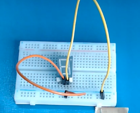
- Connect the SSD with the breadboard.
- Connect positive and negative terminals on the breadboard with wires.
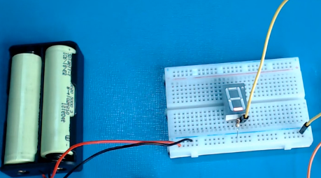
- Power up the breadboard by providing positive and negative supplies and connect a resistor at the negative terminal of the SSD.
- Connect all the wires on the rest of the terminals of the SSD and turn on the LED’s
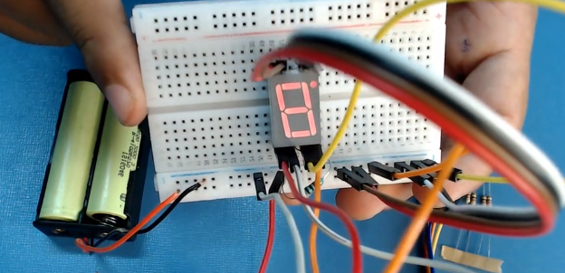
Now, you will be able to make your own seven-segment display. Hope you liked the project and were able to understand the procedure. We tried to explain the process of making the seven-segment display project in simple manner. If you have any queries related to the same, you can leave your comments below. We will be happy to answer your question.
