

About This Project
In this tutorial, we will learn how to create an Infrared Burglar Alarm using IR Sensor.
Project Info
- Programming Platform: Arduino IDE
- Difficulty: Intermediate
- Estimated Time: 1 Hr
- Category: Arduino
- Tags: Breadboard, Arduino, IR Sensor, Jumper wires, and Buzzer.
Watch the video here.
Introduction
Do you often feel insecure about strangers trying to invade your house? Have you thought of some solution to this? If not, try considering making a burglar alarm using IR sensor. A Burglar Alarm is a type of Siren that produces a sound when danger is encountered. It can also be used as an anti-theft alarm by making a simple project using Arduino and an IR sensor.
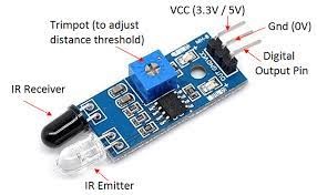
What is IR Sensor?
An infrared (IR) sensor is an electronic device that is used to detect specific characteristics like motion, heat, etc. in its surrounding by emitting/detecting IR radiations. It is a digital sensor that gives a value 0’s and 1’s or LOW and HIGH. It sends out a signal and receives it back when something blocks the delivering signal. It is a passive-type sensor. This sensor is used to measure the heat of the target and its motion.
An IR sensor comprises of two parts viz. the emitter and the receiver and this is jointly called an optocoupler or a photo-coupler. It is one of the major components we have used in making the burglar alarm project on breadboard.
Project: how to create an Infrared Burglar Alarm using IR Sensor.
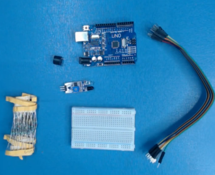
Components Required
| IMAGE | COMPONENT | QUANTITY |
|---|
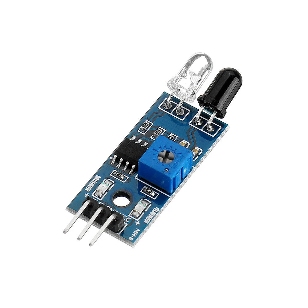
IR Sensor
1
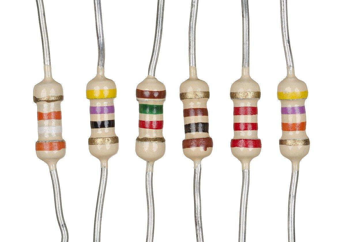
Resistor
220 ohm
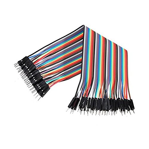
Jumper Wires
As Per Requirement
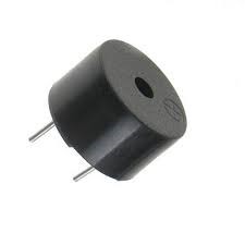
Buzzer
1
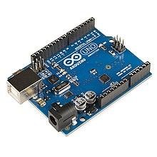
Arduino
1

USB cable A to B
1
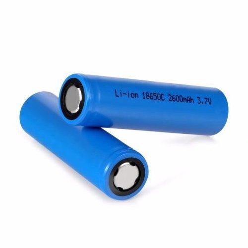
Battery
1
Building Guide
Step 1: Assembly
- Start by assembling all the components.
- Connect the IR sensor to the breadboard.
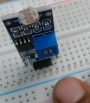
- Powering up the IR sensor using a breadboard.
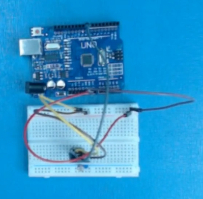
- Connect the output pin to the digital pin 8 of the Arduino.
- Connect the buzzer on the digital pin 7 of the Arduino.
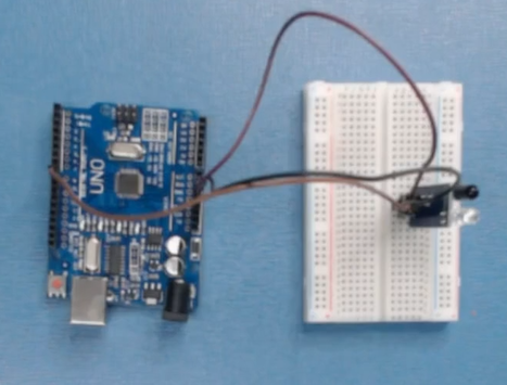
Step 1: Circuitry of the Robot
- Powering the components
- Powering the IR sensors
- VCC to 5V
- GND / to GND
- Output to digital pin 8
- Connecting the Buzzer
- Output to digital pin 7
- 5V to 5V
- GND to GND
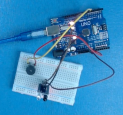
Step 2: Calibrating IR sensor
- To test the IR Sensor and ensure that it is working correctly connect the VCC to a 5v power source and GND. Move an object within a foot of the front of the Ir sensor and the D0-LED should light up.
Step 3: Logic
- If the sensor senses an object then the analog reading value will increase.
- And if the reading value reaches the threshold value then the buzzer will start and create an alarm.
Step 4: Code
- Start by declaring the pins we are using
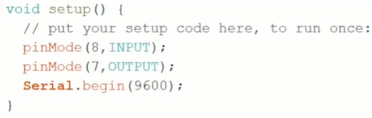
- Fetching the values and showing it in the serial monitor.


- Applying a conditional operation to control the buzzer.

The following code will help you to make an Infrared Burglar Alarm
Code
DESCRIPTION
DOWNLOAD CODE
Infrared Burglar Alarm using IR Sensor Code
Did you find this project interesting? Do share your views with us by leaving your comments below..
