

About This Project
Learn how to create a color detecting bot using the Arduino bot
Project Info
- Programming Platform: Arduino IDE
- Difficulty: Intermediate
- Estimated Time: 2 Hrs
- Category: Arduino, Robotics
Introduction
We all know that white light is made up of 3 primary colors viz. red green blue. Each color has a different wavelength and when combined with each other forms different colors. Today, we are going to learn about the TCS230 color detecting bot sensor and how it helps in recognizing the colors using an Arduino board.
What is an LCD display?
A liquid Crystal Display commonly known as LCD is a type of flat panel display that uses liquid crystals for operation. LEDs are used by consumers and businesses in electronic devices such as televisions, smartphones, computer monitors, and instrument panels. Here, we are using 8 x 2 LCD on which the RGB values get displayed.
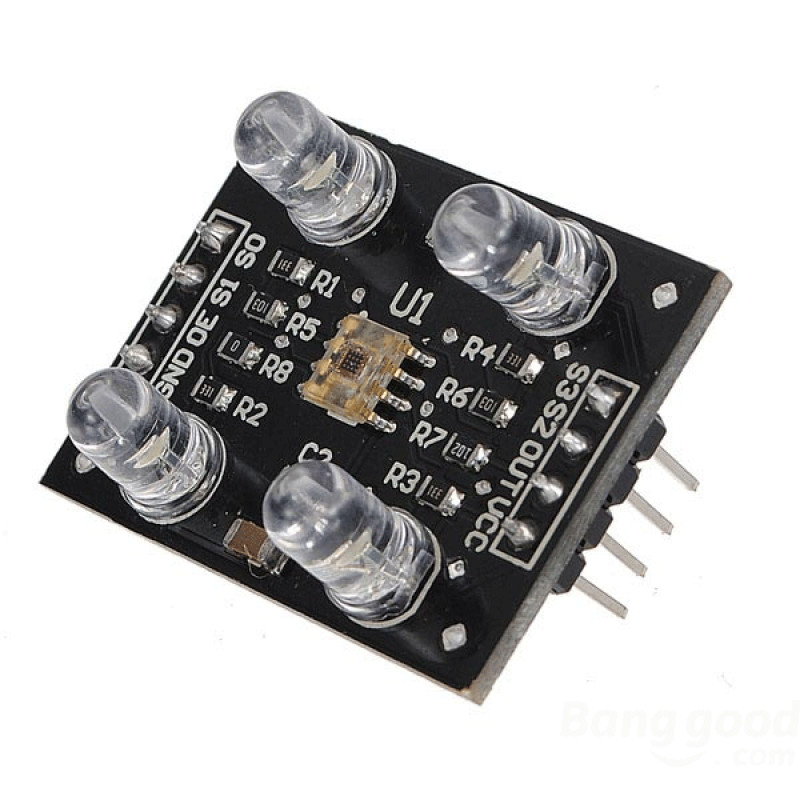
About TCS230 Sensor
The TCS230 color detecting bot sensor senses the color of the object with the 8 x 8 array of photodiodes. The Current-to-Frequency Converter is used to convert the readings from the photodiodes into a square wave with a frequency directly proportional to the light intensity. Arduino board is used to read the square wave output and get the results.
The photodiodes in this sensor have three different colors (16 of them have red filters, other 16 have green filters, another 16 have blue filters and the other 16 photodiodes are clear with no filters). 16 photodiodes are connected in parallel and two control pins – S2 and S3 help users in selecting which of them will be read. Besides, there are two other pins viz. S0 and S1, using which the scaling of output frequency can be done.
Components Required
| IMAGE | COMPONENT | QUANTITY |
|---|
Color Sensor
1
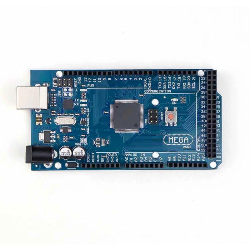
Arduino Mega
1
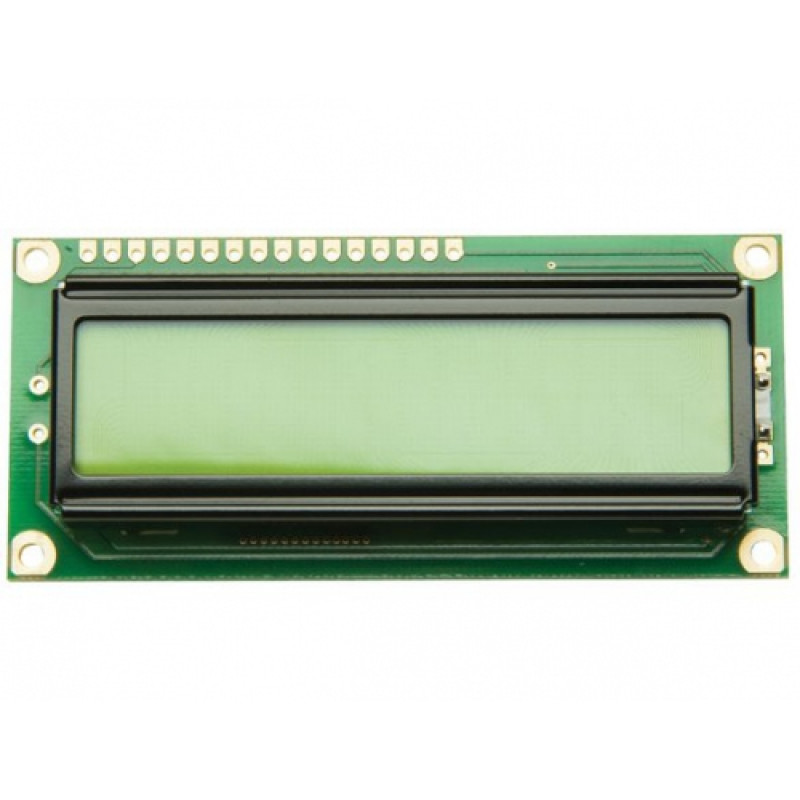
16*2 LCD display
1
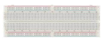
Breadboard
1
Jumper Wires
As Per Required

USB A to B
1
Building Guide
Step 1: Logic
- The TCS230 detects color with the help of an 8 x 8 array of photodiodes, of which sixteen photodiodes have red filters, 16 photodiodes have green filters, 16 photodiodes have blue filters, and the remaining 16 photodiodes are clear with no filters.
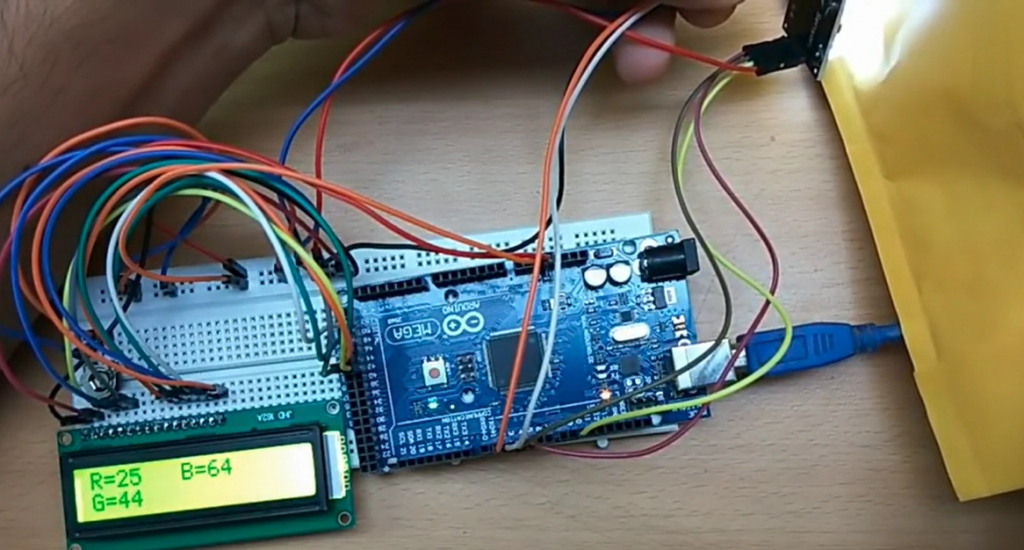
Step 2: Circuitry of the Robot
- Powering the components
- Powering the Color sensors
- VCC to 5V
- GND / to GND
- OE to GND
- S0 to 2
- S2 to 3
- S3 to 4
- S4 to 5
Step 3: Code
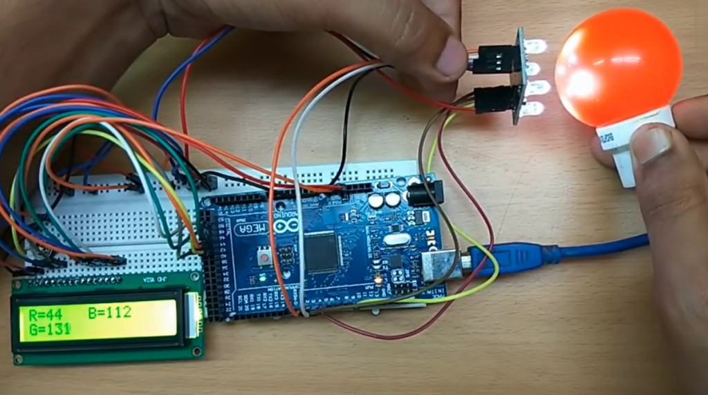
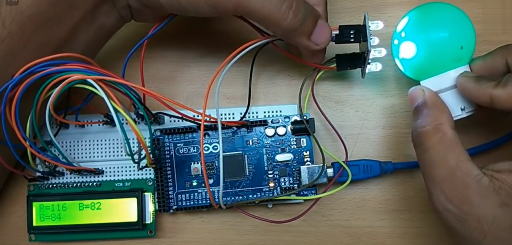
- The RGB values are shown in the 16*2 LCD display.
The following code will help you to make the Hand Gesture Controlled Robot:
The following code will help you to make the Color detecting Bot.
Code
DESCRIPTION
DOWNLOAD CODE
Color Detecting Bot Code
You will be amazed to see how a simple color detecting bot sensor works and shows the color and color code on the 8 x 2 LCD screen.
