

About This Project
In this tutorial, we will learn about Series & Parallel Circuit Combination Of Load.
Project Info
- Difficulty: Easy
- Estimated Time: 30 min
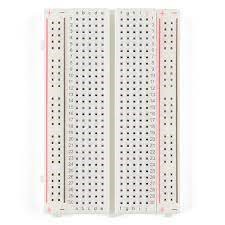
- Category: Breadboard
- Tags: LED, Breadboard, Battery, Resistor, Jumper wire.
Watch the video here.
Introduction
An electric circuit contains conductors, resistors, switches, and a power source. The electricity flows from higher potential to lower potential. The different components of the electric circuit can be connected in multiple ways thereby producing a network that might be a complicated one. As a solution to this, solving resistors in series and parallel becomes important.
Resistors are the electronic components used to resist the flow of electricity and control or limit the electricity in a circuit. Increasing circuit resistance reduces the flow of electricity. Resistors are used throughout electronics to limit the amount of current that flows.
LED (light-emitting diode) is a semiconductor device that emits light when an electric current flows through it. When current passes through an LED, the electrons recombine with holes emitting light in the process. LEDs allow the current to flow in the forward direction and blocks the current in the reverse direction.
For understanding the Circuit Combination Of Load, we need to first understand what is a series and parallel combination of circuits.
What is a Series Combination?
When two or more Resistors are connected to each other by the end-to-end method then this type of method of connection is called the series combination of resistors. The total number of resistors connected in series are equal to the sum of all individual resistances.
RN(series)=R1+R2+R3+…….+RN
What is a Parallel Combination?
If there are more than one path for the flow of current in a circuit, then the combination of resistances is called a parallel combination. Common voltage is given across all the connected resistors.
Rn(parallel)=1/R1+1/R2+1/R3……+1/Rn
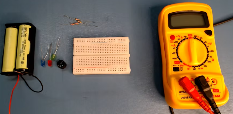
Components Required
| IMAGE | COMPONENT | QUANTITY |
|---|
1
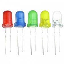
LED’s
34
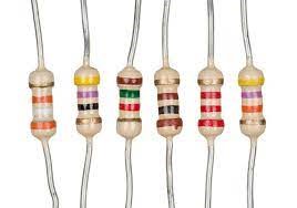
Resistor
12
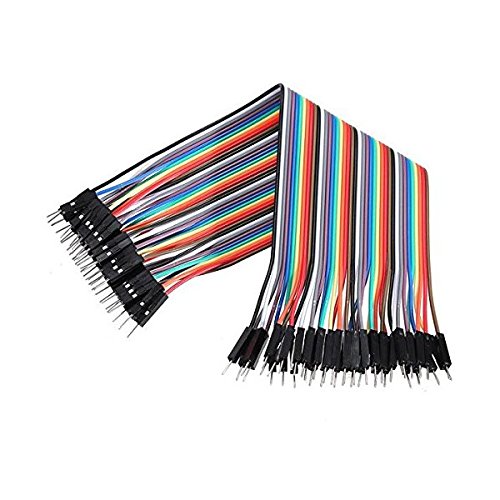
Jumper Wires
56

Battery
2
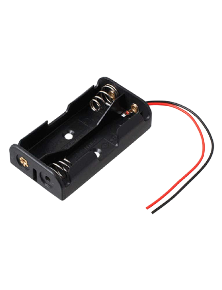
Battery Holder
1
Building Guide
Step 1: Circuitry of the Breadboard
- Powering the components
- Powering the LED
- VCC to 5V
- GND / to GND
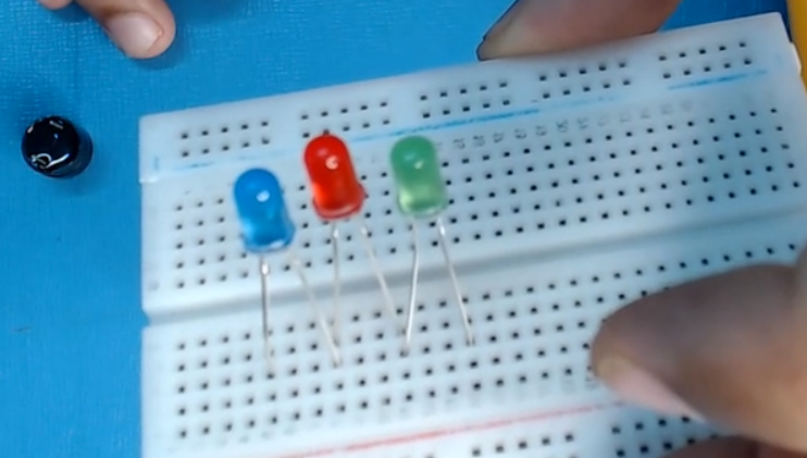
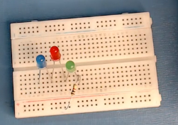
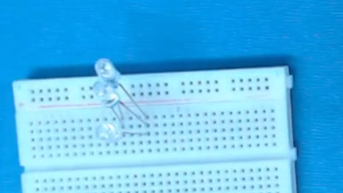
Step 2: Assembly
- Assemble all the components required for the project.
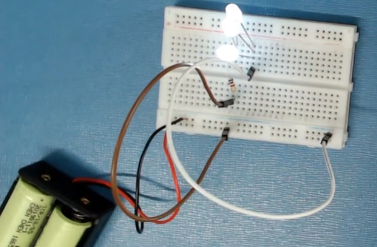
Series Connection
- Connect the LEDs in series like the first LEDs negative terminal to the second LEDs positive terminal then the second LED’s negative terminal to the third LEDs positive terminal.
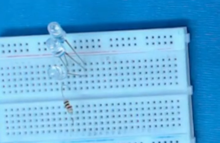
- Connect the resistor with any LED terminal.
- Power up the breadboard by providing positive and negative supplies from the battery.
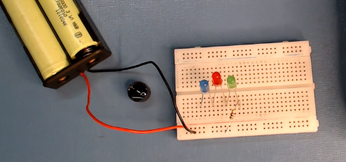
- Now connect a wire from the last LED terminal to the power rail and glow the light.
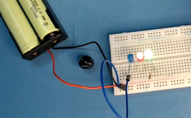
Parallel Circuit
- Connect the LEDs one after another in the vertical line by making parallel lines.
- Now, connect the resistor at one end of the LED.
- Now, connect the jumper wires and battery in positive and negative rail on the breadboard then glow the LEDs.
This way you will be able to see the working of load in series and parallel combinations. Hope you learned what is Circuit Combination Of Load. Have any questions related to the Circuit Combination of Load – Parallel and Series? Leave your comments below and we will be happy to answer you.
