
About This Project
Learn about the metal chassis and the mechanical constructions of a manual robot. In addition, we will learn about the circuitry of wire controlled robot.
Project Info
- Difficulty: Beginner
- Estimated Time: 2 Hr
- Category: Mechanical Robot
Watch the video for wire controlled robot construction building here.
Introduction
We will be creating a robotic car (Wire Controlled Robot) that can be controlled using the remote. The 3-wheel drive includes two wheels and one castor wheel. We will learn about the concept of the differential drive. When the connection is done properly, this manual bot can be moved easily using the DPDT switch.
What is BO Motor?
BO Motor is one of the major components of wire controlled robot project. It is a lightweight DC geared motor that gives good torque and RPM at low voltages. The BO motor has the ability to run at approximately 150 RPM when driven by a single Li-Ion cell. The BO motor is used for lightweight applications and is available in different torque and RPM.
Introduction to Differential Drive
The differential drive is a two-wheeled drive bot with independent actuators for each wheel. Its direction can be changed by changing the relative rate of rotation of its wheels and does not require an additional steering motion.
DPDT switch: A Double Pole Double Throw (DPDT) switch is a switch that has 2 inputs and 4 outputs. Each input of the switch has two corresponding outputs that it can connect to.
Components Required
| Sr.no. | Image | Component | Quantity |
|---|---|---|---|
| 1. |  |
BO Motor | 2 |
| 2. | 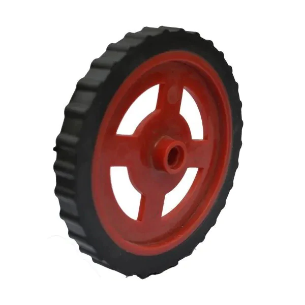 |
Wheels | 2 |
| 3. | Ball caster wheel | 1 | |
| 4. |  |
Battery | 1 |
| 5. | Connecting wire | As per requirements | |
| 6. | 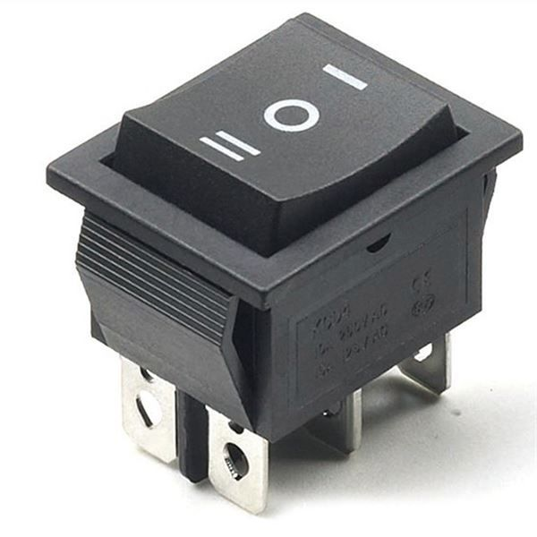 |
DPDT switch | 2 |
| 7. | 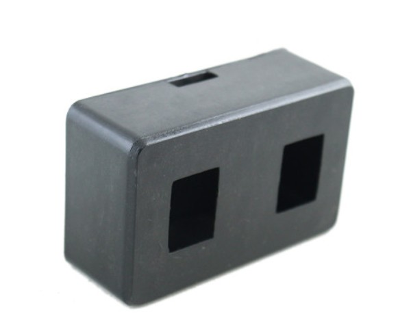 |
DPDT Switch box | 1 |
| 8. | 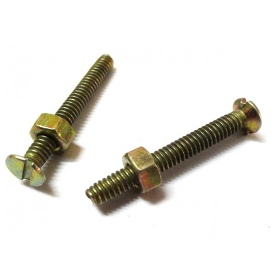 |
Nuts and Bolts | 8 |
| 9. | Screwdriver | 1 | |
| 10. | 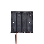 |
4-slot Battery holder | 1 |
Building Guide
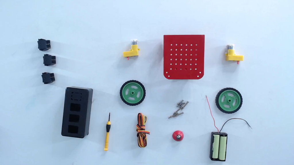
Step 1: Collect all the components (Metal chassis, DC motor, DPDT switch, wires, robot motor wheel, Battery, Battery holder) required for making wire controlled robot.
Step 2: For the mechanical construction of wire controlled robot, follow all the steps given below.
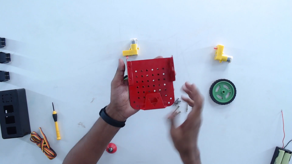
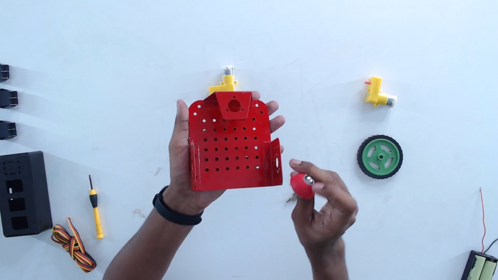
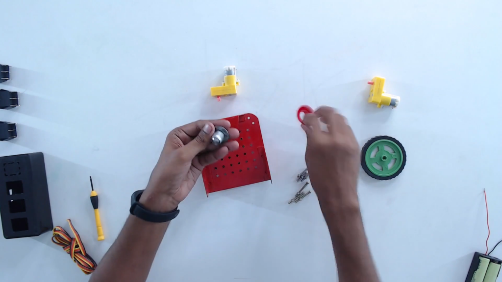
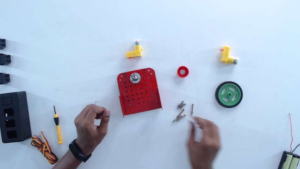
Step 3: Flip and place the castor wheel on the mounting holes. Fix with screws.
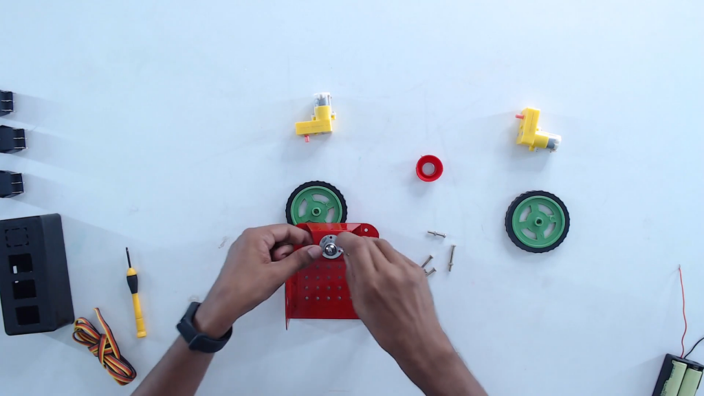
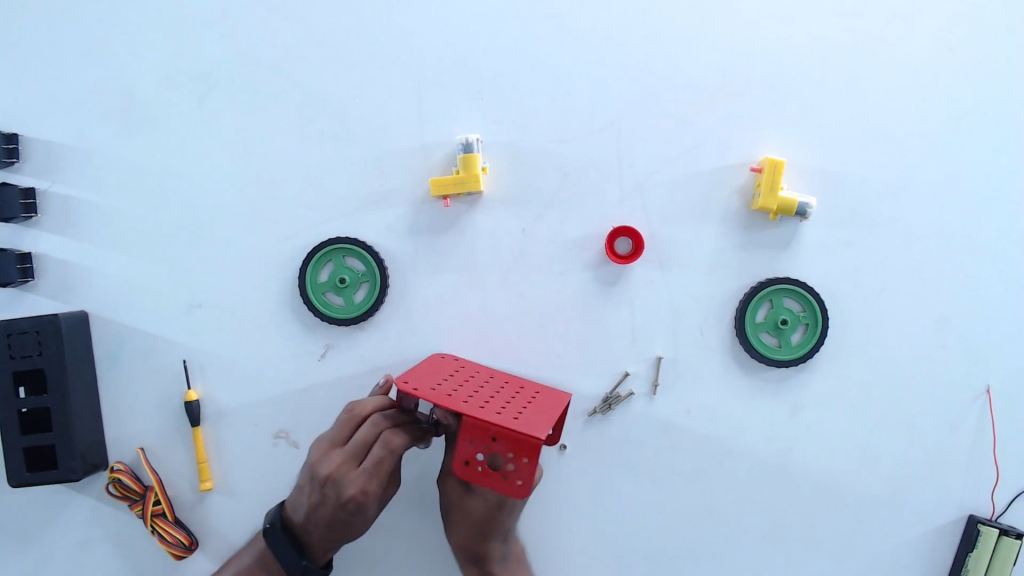
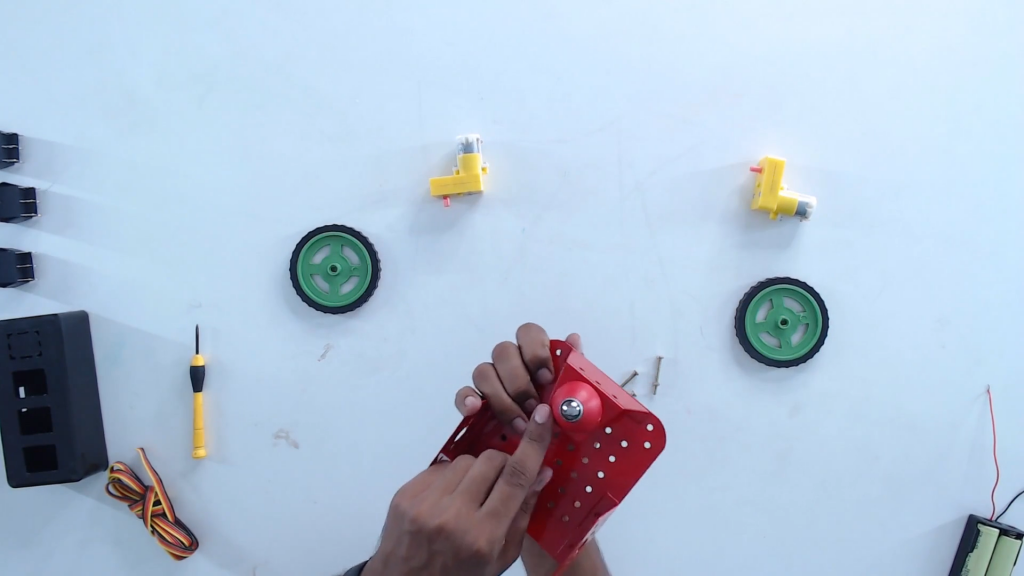
Step 4: Turn the lower base plate back to initial orientation.
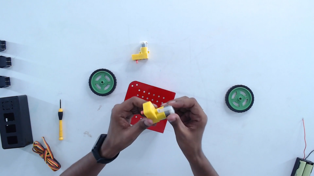
Step 5: Mount the BO motors on the chassis.
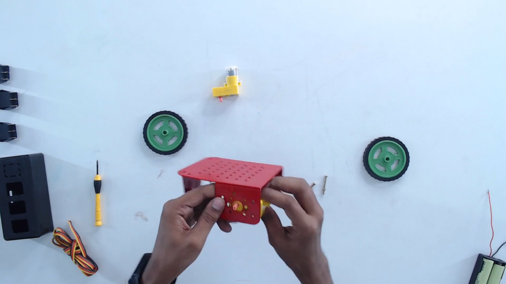
Step 6 Tighten the BO motors using nuts and bolts provided in the kit.
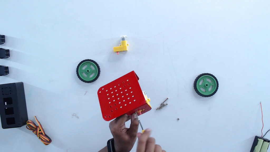
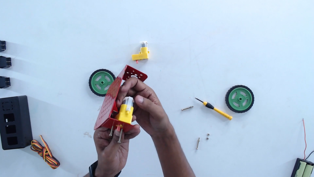
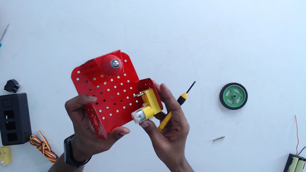
Step 7: Attach the wheels with the BO motor shaft.
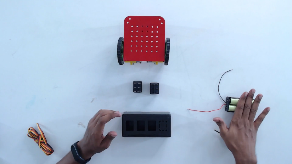
Step 8: Connect the wires with the left and the right BO motor. Now, we are ready to make the connections.
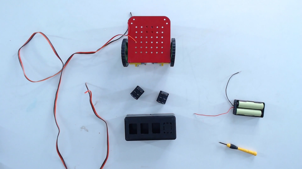
Step 9: Make the connections as per the below-given instructions. There are six pins in the DPDT switch. We need to provide the power supply in pins B and E. Connect the motors at pins A and D. Make a cross-connection between the pins A & F and D & C. Do the same for the next DPDT switch.
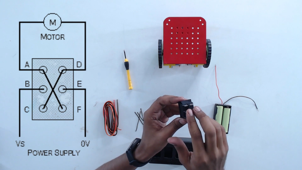
Step 10: Connect the same way as it is in the above-given connections.
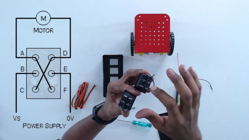
Step 11 Put the DPDT switches inside the switch box
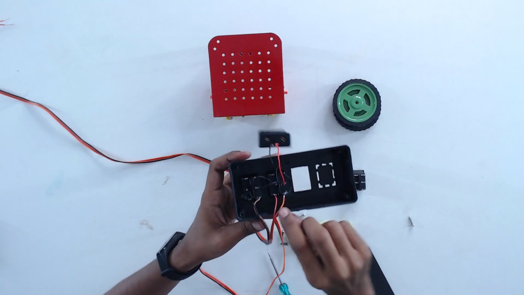
Step 12: Solder/connect the wires to the terminals of the motors.
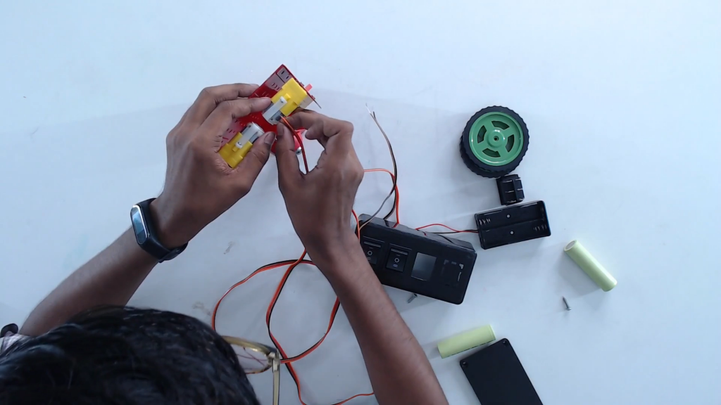
Step 13: Connect the wires in such a way that the right switch to the right motor and the left switch to the left motor.
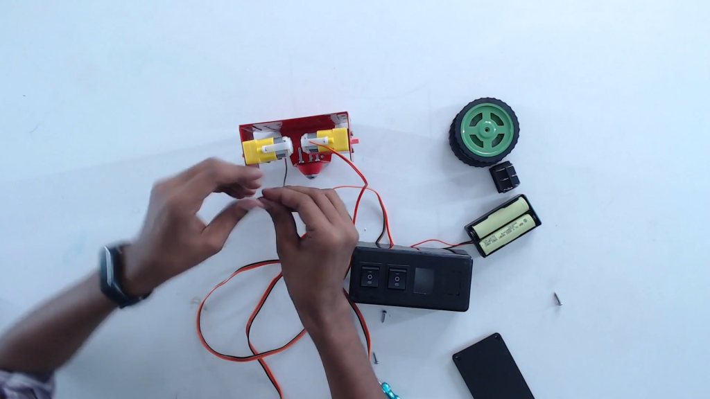
Step 14: When all the connections are done, close the switch box and start the test run by pressing both the switches at the same time to forward and backward.
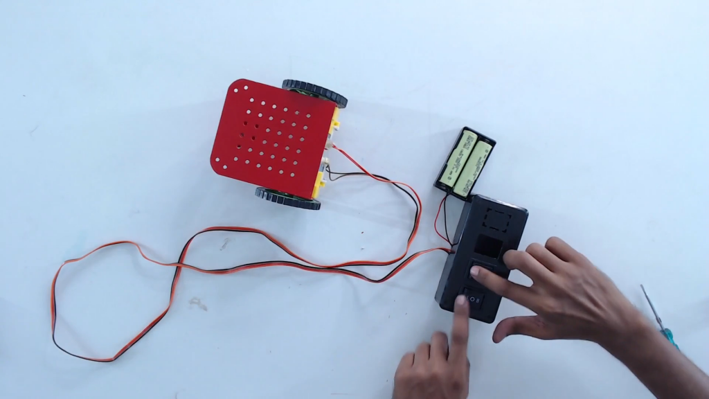
Step 15: To go left and right, press both the switches in the opposite directions.
Have you tried your hands on wire controlled robot project? Isn’t it interesting? Have your say by leaving your comments below.
Leave A Comment
Related Posts
Coding is generally considered a boring activity. After all, who wants to sit in front of a computer all day writing in a language that can’t even be read? But that is not all there is to code. It can be used for some really fun coding facts stuff, and there is so much amazing work that you can do only if you knew how to code.
5 Coding Facts That Blow Your Mind
Let us look at five great fun coding facts you might not know about coding.
You Can Make Games With Code
Coding is an umbrella term for the scores of languages and their versions that programmers use to make their applications. We have all played games, on consoles, our mobile phones, or our desktop computers and laptops, at some point in our life. It might not surprise you to know that these games are also created using code. The complex physics of the characters in these games, the design of the environment of the games, and each minute movement in the games have a piece of code behind them.
Game designers typically write in languages such as C++, C#, and Java. These are also some of the most popular kids coding languages, especially for children who like gaming. Coding courses are available widely in all of these languages and the broad domain of game design.
You Do Better At School If You Code
Making games and indulging in the fun applications of coding is all fine, but coding can have great advantages at school as well. Once you start taking classes that teach coding for kids, you will realize that coding requires a lot of brainpower as well. Coding even for the most fun tasks requires you to think quite a bit, and this sharpens your mind and increases your capability to think logically.
This logical capability can be of a lot of use to you at school. Especially in subjects like mathematics, you might find yourself topping the class simply because of the practice you got during coding! In fact, coding and mathematics have a kind of symbiotic relationship – what you learn in maths comes of use in code and vice versa.
You Can Follow Your Interest Using Coding
Regardless of what your favorite subject is, or what fields you are interested in, you will find a use for code everywhere. Be it through developing software, creating an all-new app, making a game, or building a simple utility, you will find that coding facts can be a way to enable you to follow your interests through a different path.
All subjects from science to social studies and from mathematics to philosophy use coding in some way for research or education. Be it sports or music, art or architecture, utilities that are made using code are prevalent in every field that you can think of. Taking simple online coding courses can qualify you and build your interest in creating such utilities.
You Can Predict Future Events Through Code
Did you know that predicting the future is an application of coding! Predictive modeling is a field of programming in which code is used to try and predict what will happen in the future on the basis of events that took place in the past. It uses concepts of artificial intelligence and machine learning to create algorithms that learn the behavior of past data and determine the course of future data.
Predictive modeling is one of the most futuristic applications of code and is used to determine everything from the next movie you will like on Netflix to whether it will rain tomorrow. You can opt for closing classes in machine learning to know more about the field, and create your own utilities to predict the future!
Coding Is Free!
You don’t need any sophisticated apparatus except your laptop for coding. All you need is the will to learn more and follow your interests through code. To learn to code you do not need to go to a special school or have any special capabilities. You can opt for free coding classes for kids which are held completely online and follow a completely hands-off approach in helping kids learn to code. There are also a vast number of coding sites for kids on which they can log in to learn basic coding facts for kids without even having to enroll in a class.
Conclusion
The future is already being written, and it is being written in code. Coding for kids classes can help kids of all ages currently going to school not just learn to code but also to have fun in the process. The above applications of code can be a major stepping stone to build the interest of kids in coding, after which they can hone their interests and new skills on even more advanced applications. A platform such as Learningbix can be an excellent way for you to get started.

