

About This Project
In this project, we will be learning about how to take input from the Flex Sensor with the help of Arduino.
Project Info
- Programming Platform: Arduino IDE
- Difficulty: Intermediate
- Estimated Time: 1 Hrs
- Category: Arduino
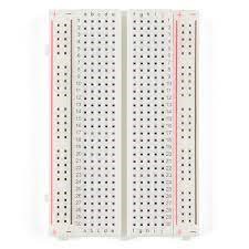
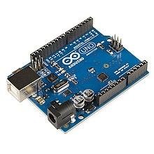
- Tags: Flex Sensor, Arduino, Jumper Wires (Male & Female), BreadBoard.
Watch the video here.
Introduction
In this technological era, we have seen and heard a robotic arm controlled by the human hands. That control is done using the sensor called Flex Sensor is a two terminals analog sensor that senses when we bend or curve from the normal condition. It is a resistance-based sensor plated with a copper layer upon the flexible substrate. This sensor is available in two sizes i.e. 2.2 inch and 4.5 inch.
These may vary in size but the basic function is the same. Besides, these sensors can be categorized on the basis of medium, low or high resistance and one may pick one depending on the requirement. These sensors do not have polarized terminals like diodes which is why there is no positive and negative. It can be used if we want to check if the surface of the device or component is leveled or not. It can also be used to measure the flex/bent/angle change of any device. The internal resistance of the flex sensor changes linearly with its flex angle.
Applications of Flex Sensor
As mentioned above, this type of sensor can be used in applications where accurate measurement of motion or angle of device needs to be measured. This sensor can be used in robotics, automotive, medical instruments, motion control, musical instruments, fitness devices, computer peripherals, and more. With this project, we will learn about Flex Sensors, how it works, how to interface this sensor with Arduino, and control devices like LED, gesture-controlled devices, and more.
Project: How to use a flex-sensor for analog input with arduino.
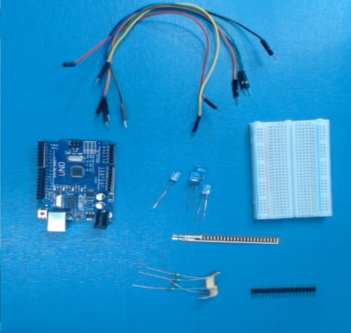
Components Required
| IMAGE | COMPONENT | QUANTITY |
|---|
1
1

Flex Sensor
As Per Requirements
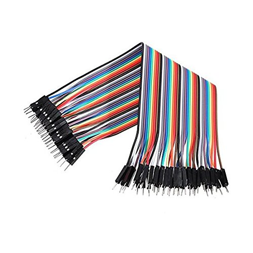
Jumper Wires
1
Building Guide
Step 1: Assembly:
- Gather all the required components.
Step 2: Circuitry:
- Analog Pin-A0 to Flex Sensor Pin1
- GND to 220 Ohms resistor to VCC pin
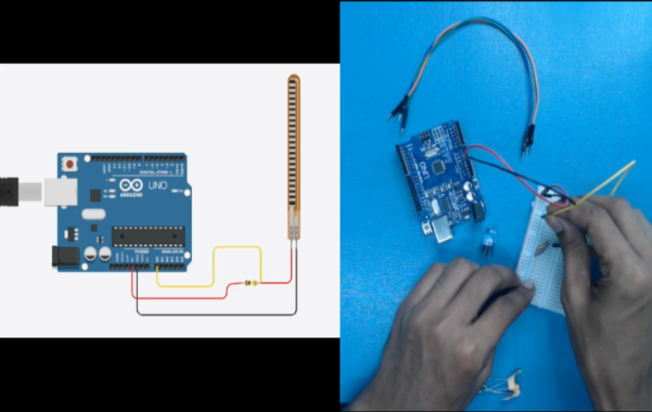
Step 3: Connect the Arduino with a USB cable and upload the program.
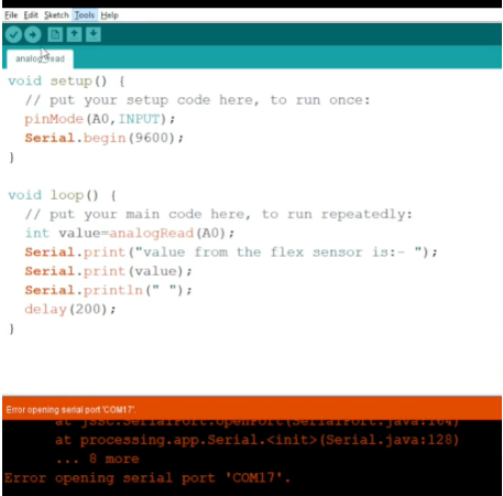
CODING:
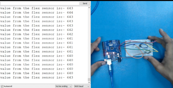
Step 4: Go to the Serial Monitor to see the value fetched by the sensor in normal conditions.
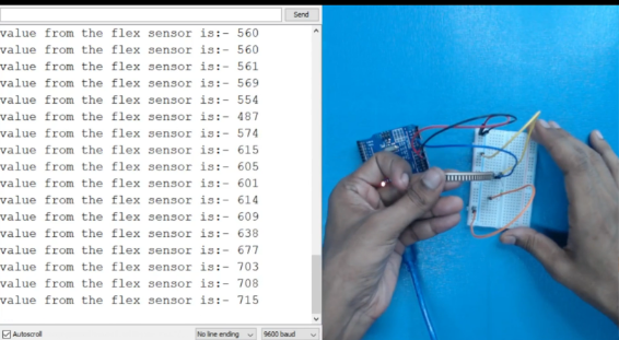
Step 5: Now, bend the sensor to see the change of value. We can see that the value is increasing as we bend towards the backside. Likewise, if we bend towards the front side the value will be decreased.
The following code will help you in making a Flex Sensor.
Code
DESCRIPTION
DOWNLOAD CODE
Flex Sensor For Analog Input Code
This way we can use flex sensor for analog input. Hope you learned something interesting. Stay tuned for more such interesting projects.
