

About This Project
In this tutorial, we will be learning how to create a Smart Night Lamp with breadboard.
Project Info
- Difficulty: Easy
- Estimated Time: 2 Hrs
- Category: Breadboard
- Tags: LED, LDR sensor, Breadboard, Battery, Jumper wire.
Introduction
An automatic night lamp as the name suggests is a lamp that turns ON and OFF automatically without the need for human interventions. It senses the light intensity from surroundings and finds whether it’s day or night. It turns ON automatically when its dark around and it turns OFF when it receives light from its surroundings. A sensor called LDR is used to detect the light intensity. This project finds wide outdoor applications in streets, gardens, and public places where it is difficult to appoint a person to operate the lights.
In this tutorial, we have will be making a smart night lamp on our own and understand its working too.
What is an LDR Sensor?
LDR, also known as photoresistor is a device that is made up of high resistance semiconductor material. This electronic component is responsive to light, when light falls on it, then the resistance decreases, and it increases in the dark. When an LDR is kept in a dark place, its resistance is high and, when the LDR is kept in the light, its resistance will decrease. Easy to use, the Light Dependent Resistors have high sensitivity and inexpensive electronic components with no union potential. Moreover, their light-dark resistance ratio is high.
We will be using this sensor to make a smart lamp project. It is one of the key components that will be used throughout the project. Also, don’t forget to check our article on LDR. (linking)
Project: How To Build Smart Night Lamp Using breadboard
Now that we have a clear understanding of the project and the components used, let’s start the project.
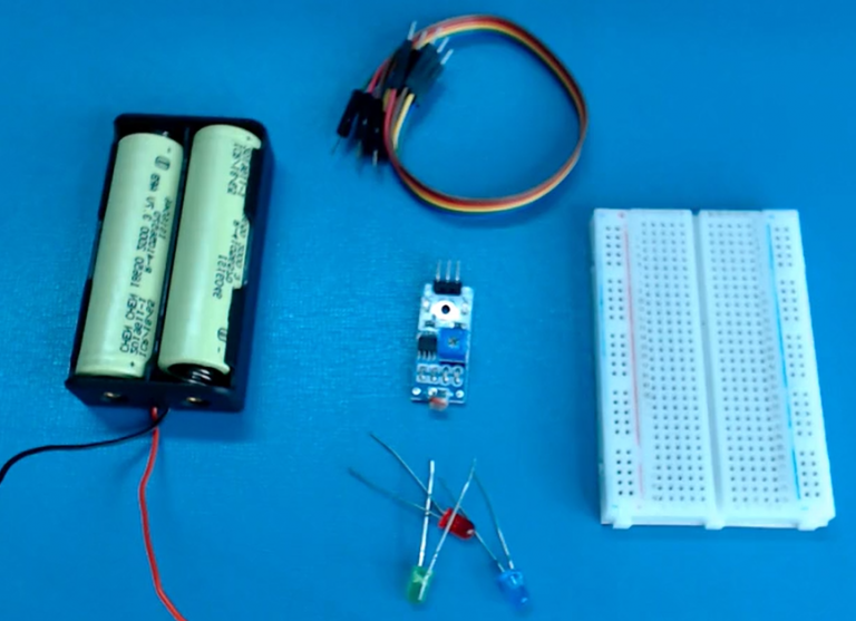
Components Required
| Image | Component | Quantity |
|---|---|---|
 |
Breadboard | 1 |
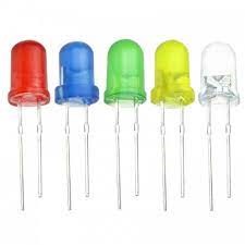 |
LED’s | 1 |
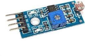 |
LDR Sensor | 1 |
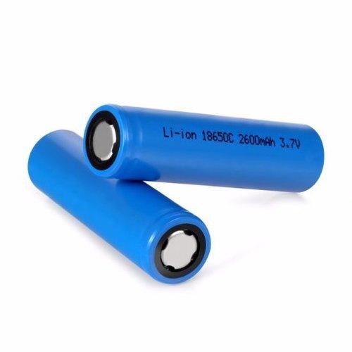 |
Battery | 1 |
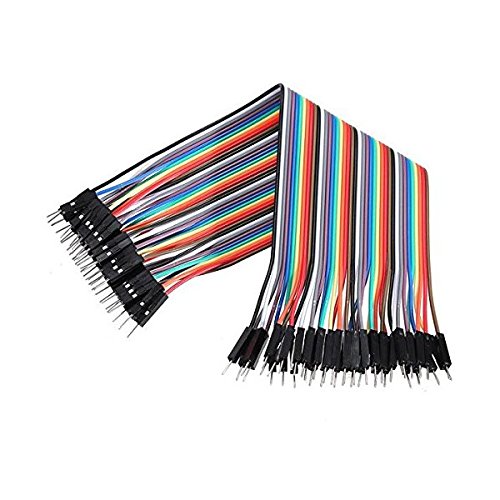 |
Jumper Wires | As Per Requirement |
Building Guide
Step 1: Circuitry of the Robot
- Assemble all the components required
- Connect LDR with the breadboard.
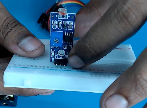
- Power up the breadboard by providing positive and negative supplies.

- Powering the LDR sensor by providing the VCC and GND.
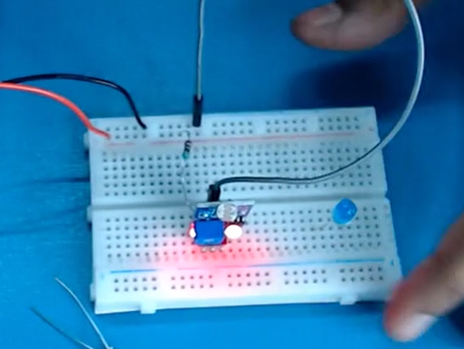
- Connect the LED with the LDR output pins.
Step 2: Circuitry of the Robot
- Powering the components
- Powering the LDR sensors
- VCC to 5V
- GND / to GND
- Output to LED positive pin.
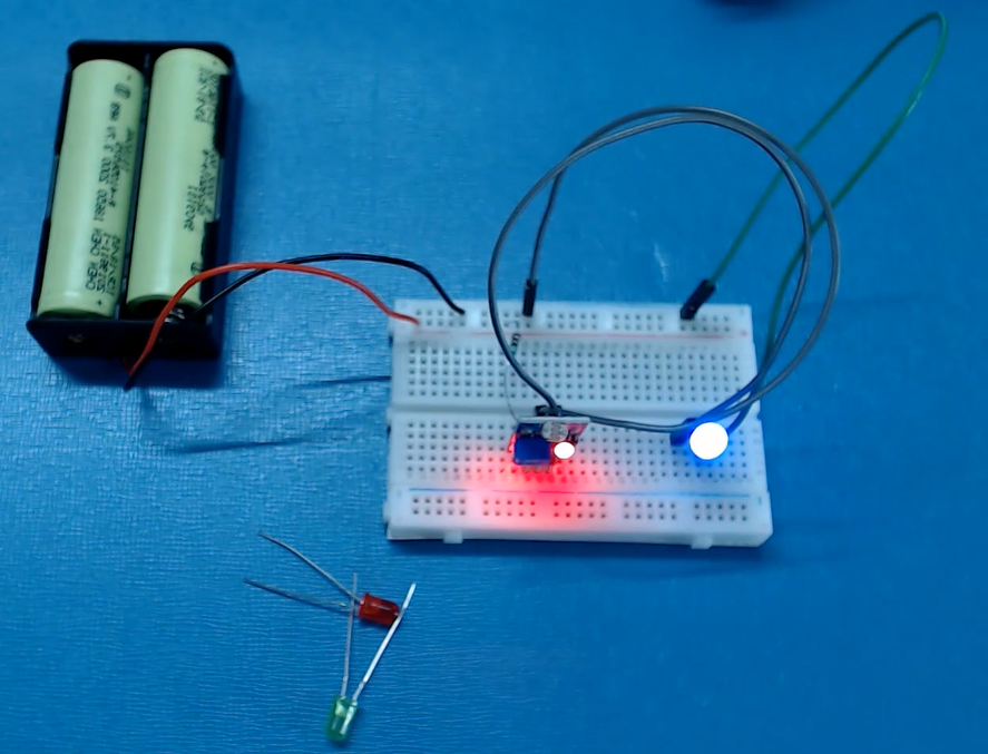
- LED pins
- Negative to GND.
- Positive to Output of LDR
That’s all for now. Your Smart Night lamp project is complete. If you have any questions related to the project, you can ask by leaving a comment below. We will be happy to help you out. Visit Learningbix
