

About This Project
In this tutorial, we will be learning how to make Blinking LED Using Monostable Mode of 555 timer IC
Project Info
- Difficulty: Easy
- Estimated Time: 2 Hrs.
- Category: Breadboard
Watch the video here.
Introduction
An automatic night lamp as the name suggests is a lamp that turns ON and OFF automatically without the need for human interventions. It senses the light intensity from surroundings and finds whether it’s day or night. It turns ON automatically when its dark around and it turns OFF when it receives light from its surroundings. A sensor called LDR is used to detect the light intensity. This project finds wide outdoor applications in streets, gardens, and public places where it is difficult to appoint a person to operate the lights.
In this tutorial, we have tried to cover different aspects of 555 Timer IC and explain its working. We will also learn the making of Blinking Led using Monostable Mode of 555 timer IC.
What is 555 Timer IC?
555 timer IC is a well-known electronic component that is used in various electronic circuits. This IC has three 5k ohm resistor connected in a voltage-divider pattern. The 555 timer comes as 8 pin DIP (Dual In-line Package) device. The 555 Timer IC has three operating modes viz. astable mode, monostable mode, and bistable mode.
What is the Monostable Mode of 555 timer IC?
Monostable multivibrator (MMV) mode of 555 timer IC commonly known as single shot mode indicates that only one state is stable and the other one is unstable. 555 timer IC remains in Stable state until the external triggering is applied. Making blinking LED using Monostable Mode of 555 timer IC is easy. easy. Let’s learn how to make Blinking LED.
Project: Making Blinking LED using Monostable Mode of 555 timer IC
Components Required
| Image | Component | Quantity |
|---|---|---|
 |
Breadboard | 1 |
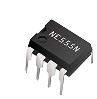 |
555 Timer IC | 1 |
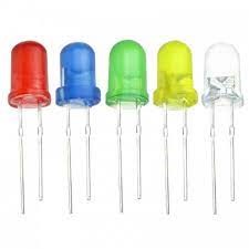 |
LED | 1 |
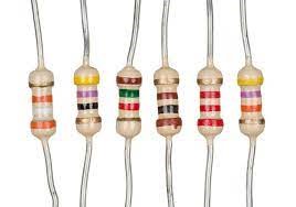 |
Resistor | 1 |
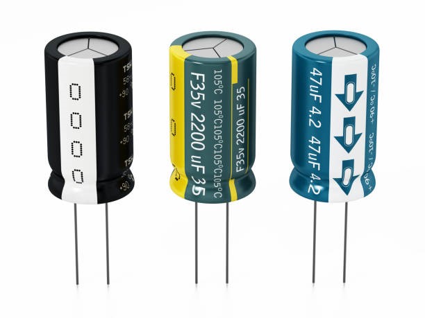 |
Capacitor | 1 |
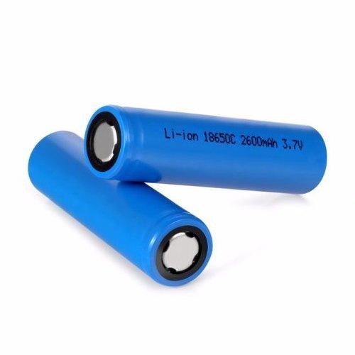 |
Battery | 1 |
 |
Jumper Wires | As Per Requirement |
Building Guide
Step 1: Circuitry of the Robot
- Powering the components
- Powering the 555 timer IC
- VCC to 5V
- GND / to GND
- Output to LED positive pin.
- LED pins
- Negative to GND.
- Positive to Output of 555 timer IC
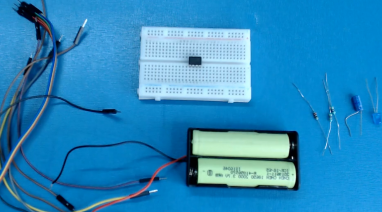
Step 2: Assembly
- Assemble all the components required
- Connect 555 timer IC on the breadboard.
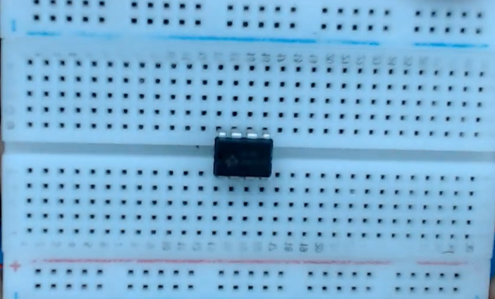
- Working and pin configuration of a 555 timer IC.

- Connect wires from the 8th pin to the negative and the 1st pin to the positive on the breadboard.
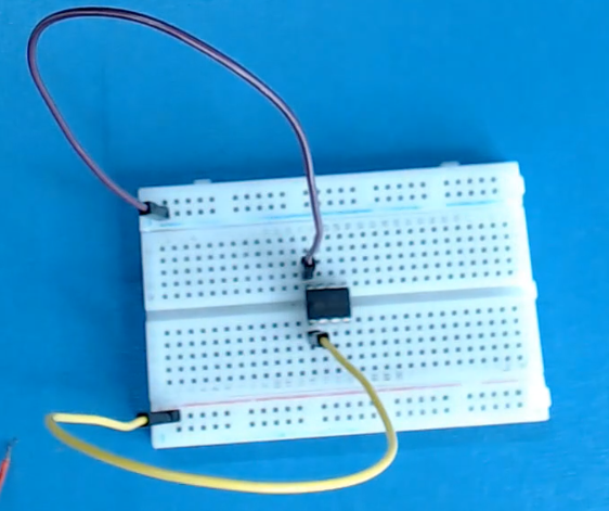
- Again from the 4th wire connect a wire to the 8th pin.
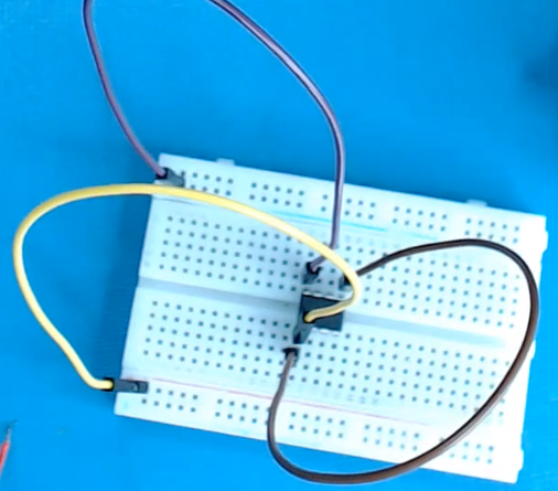
- Now, short the trigger pin with the threshold pin.

- Connect a capacitor positive pin to the 2nd pin of 555 timer IC and the negative of the capacitor to the negative on the breadboard.
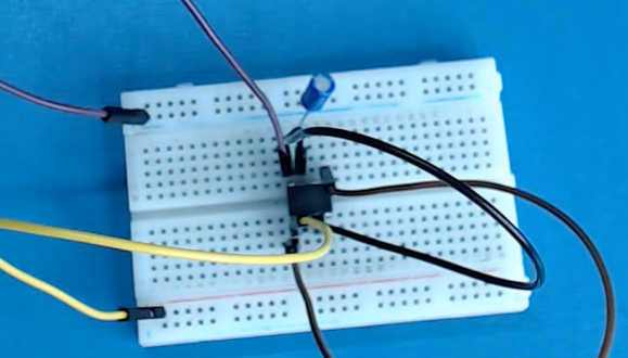
- Connect 2 resistors on the pin-6 as shown below:
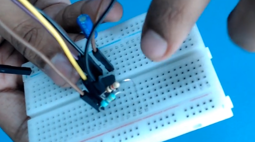
- Connect the positive terminal of the LED to the 3rd pin in 555 timer IC and negative of LED resistor to the negative on the breadboard.
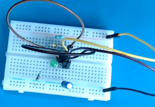
- Power up the breadboard by providing positive and negative supplies.
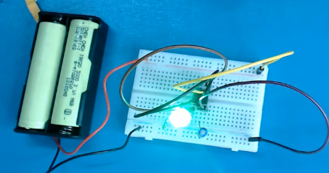
- Connect a resistor from the 7th pin and power up the breadboard.
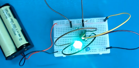
Once done, we can see the blinking led. The project we did here was done using 555 timer IC. You are sure to love the results.
