

About This Project
In this tutorial, we will learn about IoT (Internet of Things) on how to make real-time GPS location tracker through the help of NodeMCU ESP 12E by using our mobile phones.
Project Info
- Programming Platform: Arduino IDE
- Difficulty: Intermediate
- Estimated Time: 3 Hrs
- Category: IoT
Introduction
Everyday we use Google Maps to track a location. So, this tutorial is to let you understand the logic behind how it actually is working. By using the NodeMCU ESP 12E module we can make the same thing that we see on our mobile phones. We can attach this module on our luggage, vehicle, etc in order to find the location if somebody steals away our properties.
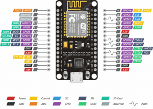
What is NodeMCU ESP 12E ?
In NodeMCU ESP 12E, there are 30 pins in total, out of which there are 17 GPIO (General Purpose Input Output) pins. There are 9 digital pins ranging from D0-D8. It’s only one analog pin “A0” which is a 10 bit ADC. The “D0” pin can only be used to read or write data and can not perform other options. It is enabled when the EN pin is HIGH. When this pin is LOW the chip works at minimum power. The board has a 2.4 GHz antenna for a long range of network, the CP2102 is a USB to TTL converter. The development board equips the ESP 12E module, containing ESP8266 a chip having Tensilica Xtensa 32-bit, LX106 RISC microprocessor which can operate ranging from 80 to 160 MHz, and Clock Frequency can be adjusted.
It has 128KB RAM, and also 4MB of Flash memory for program and data storage just enough to cope with the large strings that makeup web pages. It is an Integrated board, equipped with 802.11/b/g/n HT40 WiFi transceiver, so it can not only connect to a WiFi network and interact with the Internet. The NodeMCU ESP 12E can also set up a network of its own and allow other devices to connect directly. Due to this, ESP8266 NodeMCU makes it more versatile.
Project: IoT Based GPS Location Tracker Using NodeMCU and GPS Module
Now that we have a clear understanding of the project and the components used, let’s start the project.
Components Required
| IMAGE | COMPONENT | QUANTITY |
|---|
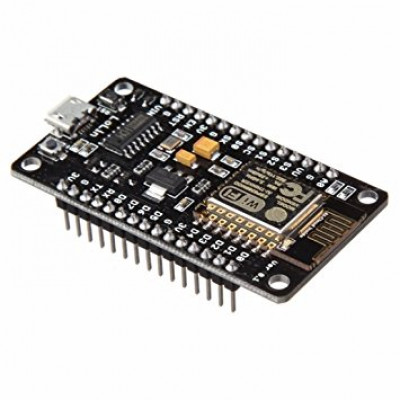
NodeMCU ESP 12E
1

Android Phone
1
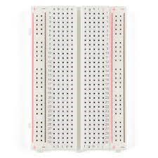
Breadboard
1
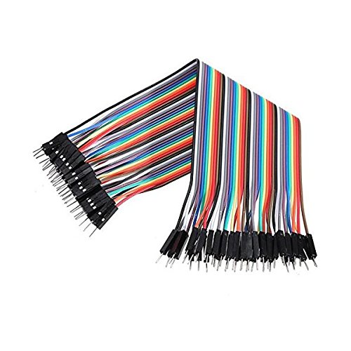
Jumper Wires
As Per Required

USB a to b
1
![]()
GPS Location Tracker module
1
Building Guide
Step 1: Assembly
- Collect all the required components and place them on the breadboard.
![]()
Step 2: Connections
- As per the below given connections.
![]()
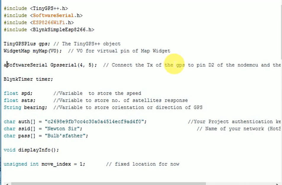
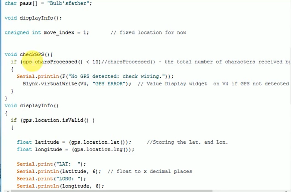
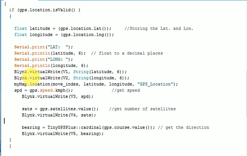
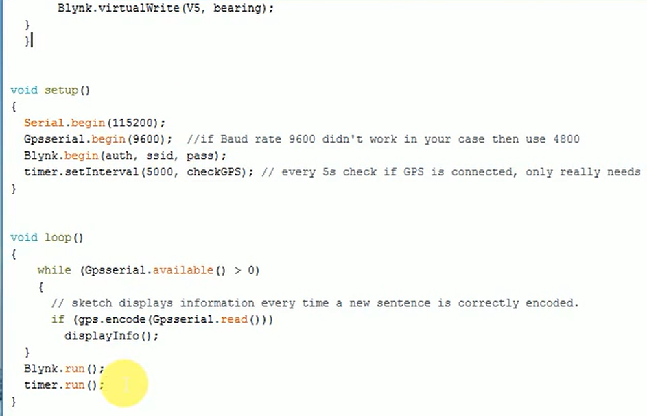
Step 3: When the connections are done, start the coding as given below.
CODING:
Step 4: Now, go to the Blynk App and create a new project. Then, set up the necessary settings.
- Generate the authentication code and replace the default code in the program with the new code received from an email ID.
![]()
Step 5: To set up the necessary settings for making real-time GPS location tracker follow the below-given steps.
![]()
![]()
![]()
![]()
![]()
- Set Longitude Pin according to the defined pin in the program.
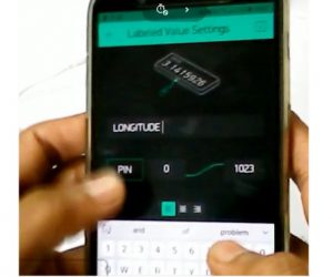
- Set Satellite Pin according to the defined pin in the program.

- Set Direction Pin according to the defined pin in the program.

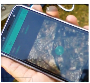
With this we have come to an end of making the real-time GPS location tracker. This is how easy it is to track the location with accurate IST time with real rime GPS location tracker. Have you tried working on the project? If yes, how was your experience? Leave your comments below to let us know.
Code
DESCRIPTION
DOWNLOAD CODE
IoT Based GPS Location Tracker Using NodeMUC Code
Libraries
Blynk Library Master
Tiny GPS Plus Master

Leave A Comment
Related Posts
Coding is generally considered a boring activity. After all, who wants to sit in front of a computer all day writing in a language that can’t even be read? But that is not all there is to code. It can be used for some really fun coding facts stuff, and there is so much amazing work that you can do only if you knew how to code.
5 Coding Facts That Blow Your Mind
Let us look at five great fun coding facts you might not know about coding.
You Can Make Games With Code
Coding is an umbrella term for the scores of languages and their versions that programmers use to make their applications. We have all played games, on consoles, our mobile phones, or our desktop computers and laptops, at some point in our life. It might not surprise you to know that these games are also created using code. The complex physics of the characters in these games, the design of the environment of the games, and each minute movement in the games have a piece of code behind them.
Game designers typically write in languages such as C++, C#, and Java. These are also some of the most popular kids coding languages, especially for children who like gaming. Coding courses are available widely in all of these languages and the broad domain of game design.
You Do Better At School If You Code
Making games and indulging in the fun applications of coding is all fine, but coding can have great advantages at school as well. Once you start taking classes that teach coding for kids, you will realize that coding requires a lot of brainpower as well. Coding even for the most fun tasks requires you to think quite a bit, and this sharpens your mind and increases your capability to think logically.
This logical capability can be of a lot of use to you at school. Especially in subjects like mathematics, you might find yourself topping the class simply because of the practice you got during coding! In fact, coding and mathematics have a kind of symbiotic relationship – what you learn in maths comes of use in code and vice versa.
You Can Follow Your Interest Using Coding
Regardless of what your favorite subject is, or what fields you are interested in, you will find a use for code everywhere. Be it through developing software, creating an all-new app, making a game, or building a simple utility, you will find that coding facts can be a way to enable you to follow your interests through a different path.
All subjects from science to social studies and from mathematics to philosophy use coding in some way for research or education. Be it sports or music, art or architecture, utilities that are made using code are prevalent in every field that you can think of. Taking simple online coding courses can qualify you and build your interest in creating such utilities.
You Can Predict Future Events Through Code
Did you know that predicting the future is an application of coding! Predictive modeling is a field of programming in which code is used to try and predict what will happen in the future on the basis of events that took place in the past. It uses concepts of artificial intelligence and machine learning to create algorithms that learn the behavior of past data and determine the course of future data.
Predictive modeling is one of the most futuristic applications of code and is used to determine everything from the next movie you will like on Netflix to whether it will rain tomorrow. You can opt for closing classes in machine learning to know more about the field, and create your own utilities to predict the future!
Coding Is Free!
You don’t need any sophisticated apparatus except your laptop for coding. All you need is the will to learn more and follow your interests through code. To learn to code you do not need to go to a special school or have any special capabilities. You can opt for free coding classes for kids which are held completely online and follow a completely hands-off approach in helping kids learn to code. There are also a vast number of coding sites for kids on which they can log in to learn basic coding facts for kids without even having to enroll in a class.
Conclusion
The future is already being written, and it is being written in code. Coding for kids classes can help kids of all ages currently going to school not just learn to code but also to have fun in the process. The above applications of code can be a major stepping stone to build the interest of kids in coding, after which they can hone their interests and new skills on even more advanced applications. A platform such as Learningbix can be an excellent way for you to get started.