

Colour Mixer
This blog describes how to use an RGB LED and a microcontroller to create a colour mixer. By adjusting the intensity of the red, green, and blue light generated by each of its individual LED chips, the RGB LED can produce a variety of colours. Each LED chip is connected to a resistor, which allows us to combine several colours to produce a broad variety of colours by adjusting the voltage across the resistance. The components needed, the circuit schematic, and the programming required to make the colour mixer are all covered in this blog. Also, we offer a sample program that shows how to use an RGB LED to produce various colours. This project can be a creative and instructive method to create vibrant light displays while learning about electronics and programming.
Materials Needed
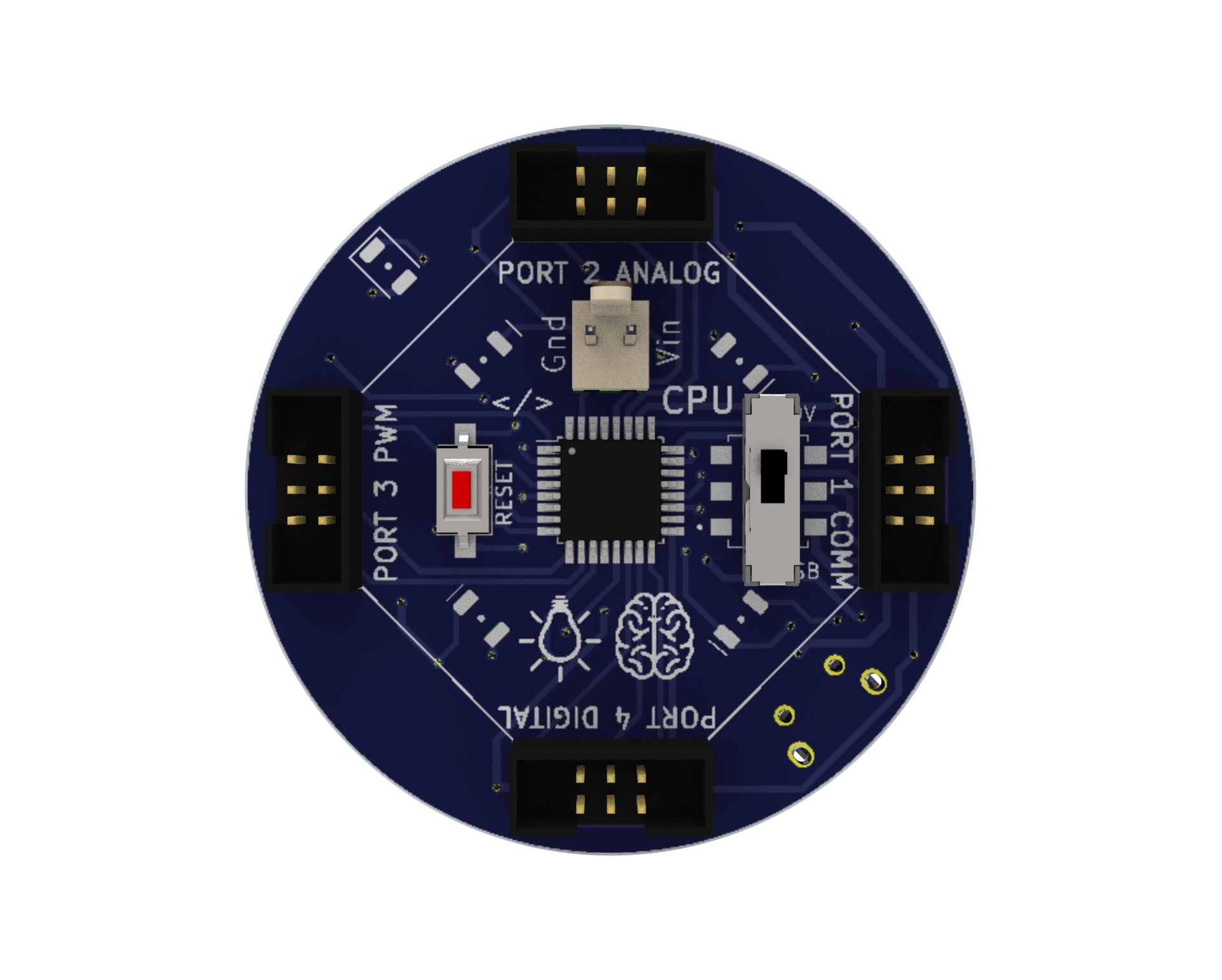
CPU: A microcontroller board that serves as the brain of the robot and can be programmed or Bluetooth-controlled for various functions of the robot.
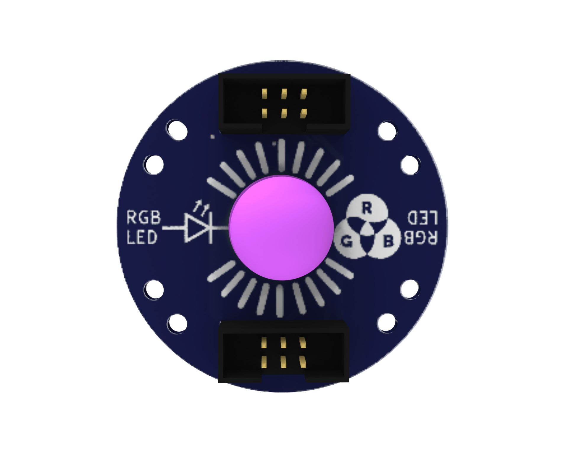
RGB LED: A component that emits different colours of light, which can be used to provide visual feedback to the user.
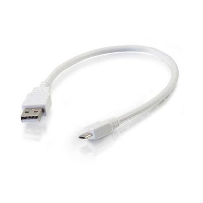
Micro USB Cable: A cable used to connect the CPU to a computer for programming or to power the CPU with a power bank.
Power Bank: A portable battery pack is used to power the CPU.
Snap Wires: Wires with pre-attached connectors that can be easily snapped on and off the components, making it easy to connect and disconnect components.
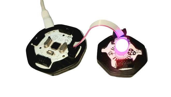
Wiring the Circuit
- Connect the RGB module to port no- 3 of CPU
- Connect the Bluetooth to port no- 1, if you are controlling the RGB led through the mobile app.
Download Arduino IDE
You can take the following actions to download the Arduino IDE:
- Go to the official Arduino website at: www.arduino.cc
- Click on the “Software” menu item in the top navigation bar.
- Select the “Downloads” option from the drop-down menu.
- Scroll down to find the section for the Arduino IDE and select the appropriate version for your operating system (Windows, Mac, or Linux).
- Click on the download link for the selected version to start the download.
- Once the download is complete, run the installation file and follow the instructions to install the Arduino IDE on your computer.
- You can launch the Arduino IDE and begin configuring your Arduino board after installation.
Install Library in Arduino IDE
Libraries are pre-written code modules that can be used to extend the functionality of the Arduino IDE and make it easier to write code for the Arduino boards. Installing a library saves time and effort as you don’t have to write the code for the required functionality from scratch. You can simply use the pre-written code in the library and modify it according to your needs.
To install the ZIP library in the Arduino IDE, you can follow these steps:
- Download the ZIP library from a trusted source such as the official Arduino library repository or a verified third-party library repository.
- Open the Arduino IDE on your computer.
- Click on the “Sketch” menu and select “Include Library” and then “Add .ZIP Library“.
- Navigate to the location where you saved the downloaded ZIP library, select the ZIP file, and click on the “Open” button.
- Wait for the installation process to complete. You will see a notification in the Arduino IDE indicating that the library was successfully installed.
Note: Download and install the libraries given below. Ignore if already installed.
Writing the Code
This code is written in C++ language and uses the modular.h library for controlling an RGB LED using a modular robot kit. Let’s go through the code step by step to understand how it works:
#include <modular.h>
Modular mybot;
In the first two lines of the code, the modular.h library is included and a new instance of the Modular class is created and named mybot. This library provides functions for controlling various components of a modular robot kit, including RGB LEDs.
void setup() {
mybot.rgbBegin(3,CC);
}
The void setup() function is called only once when the program starts. In this function, the RGB LED is initialized using the rgbBegin() function of the mybot object. The rgbBegin() function takes two arguments: the first argument is the ID of the RGB LED (in this case, 3), and the second argument is the color code of the LED (CC).
void loop() {
mybot.rgbSetBlue(3,1,100); // blue
mybot.rgbSetRed(3,0,0);
mybot.rgbSetGreen(3,0,0);
delay(1000);
mybot.rgbSetBlue(3,0,0); // red
mybot.rgbSetRed(3,1,100);
mybot.rgbSetGreen(3,0,0);
delay(1000);
mybot.rgbSetBlue(3,0,0); // green
mybot.rgbSetRed(3,0,0);
mybot.rgbSetGreen(3,1,100);
delay(1000);
mybot.rgbSetBlue(3,1,100); // purple
mybot.rgbSetRed(3,1,100);
mybot.rgbSetGreen(3,0,0);
delay(1000);
mybot.rgbSetBlue(3,1,100); // cyan
mybot.rgbSetRed(3,0,0);
mybot.rgbSetGreen(3,1,100);
delay(1000);
mybot.rgbSetBlue(3,0,0); // yellow
mybot.rgbSetRed(3,1,100);
mybot.rgbSetGreen(3,1,100);
delay(1000);
mybot.rgbSetBlue(3,1,100); // white
mybot.rgbSetRed(3,1,100);
mybot.rgbSetGreen(3,1,100);
delay(1000);
}
The void loop() function is where the main program logic is written. In this function, the RGB LED is set to different colors using various functions of the mybot object.
The rgbSetBlue(), rgbSetRed(), and rgbSetGreen() functions are used to set the intensity of the blue, red, and green components of the LED respectively. These functions take three arguments: the first argument is the ID of the LED, the second argument is the intensity value (0 for off, 1 for on), and the third argument is the intensity level (0-100).
The delay() function is used to introduce a delay of 1000 milliseconds (1 second) between each color change.
In summary, this code initializes an RGB LED using a modular robot kit and then changes the color of the LED to different colors in a loop. Each color change lasts for 1 second before changing to the next color.
Full Code for Colour Mixer
Testing?
Here are some points to test the above project:
- Make sure all components are properly connected to the Arduino board and the modular shield.
- Upload the code to the Arduino board using the Arduino IDE.
- Make sure the power source is connected and turned on.
- Verify that the RGB LED connected to pin 3 on the modular shield is working properly and displaying the expected colours.
- Observe the LED’s behavior for any unexpected issues, such as flickering, dimming, or not displaying the correct colours.
- Test the delay time between colour changes to ensure it matches the desired interval.
- Adjust the code and components as necessary to achieve the desired result.
- Repeat the testing process until the project is working as intended.
- Document any issues encountered and their solutions for future reference.
- Enjoy the finished project!
Conclusion
In conclusion, the code uses the modular.h library to control an RGB LED module connected to an Arduino board. By setting the appropriate values of red, green, and blue, the LED can be made to emit different colours with colour mixer. This code demonstrates how easy it is to use the modular.h library to control various aspects of a robot, making it a powerful tool for robotics enthusiasts and professionals alike.
