

Obstacle avoiding robots are autonomous devices that are capable of detecting and avoiding obstacles in their path using sensors. These robots are useful in various applications, such as surveillance, exploration, and search and rescue operations. In this tutorial, we will build an obstacle avoiding robot using a sonar sensor, a motor driver, two BO motors, and a three-wheel drive system, all controlled by a single CPU.

Materials Needed
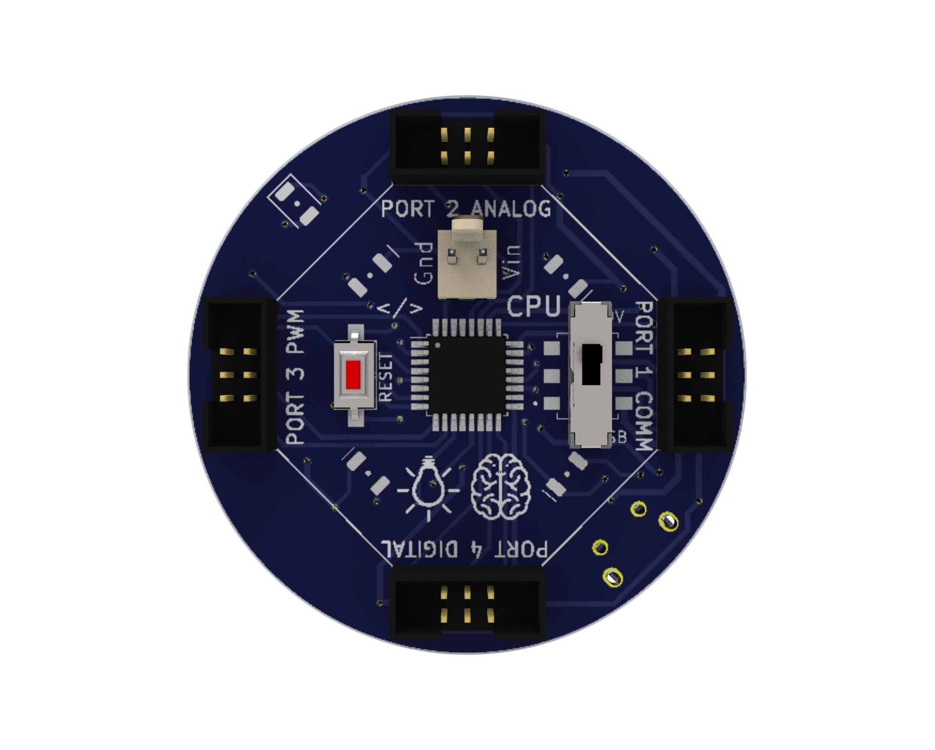
CPU: A microprocessor board used as the robot’s brain that may be programmed or Bluetooth-controlled to do a variety of tasks. We have four ports on this board, and they are each used for various input and output tasks by connecting to various electronic parts.
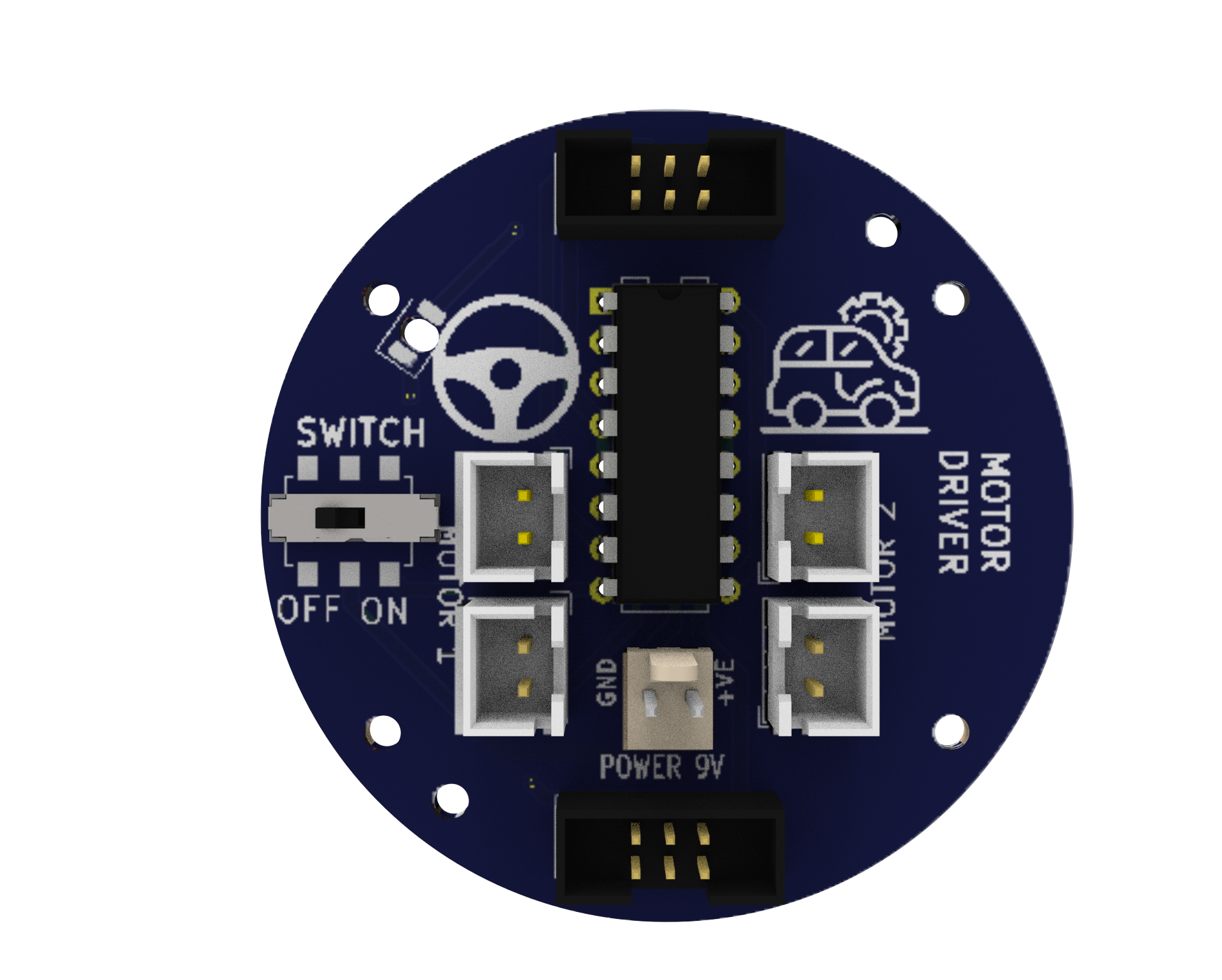
Motor Driver: A circuit that enables the robot to regulate the motors’ speed and direction. It uses a separate 9V battery to supply the motors with the necessary power and voltage.
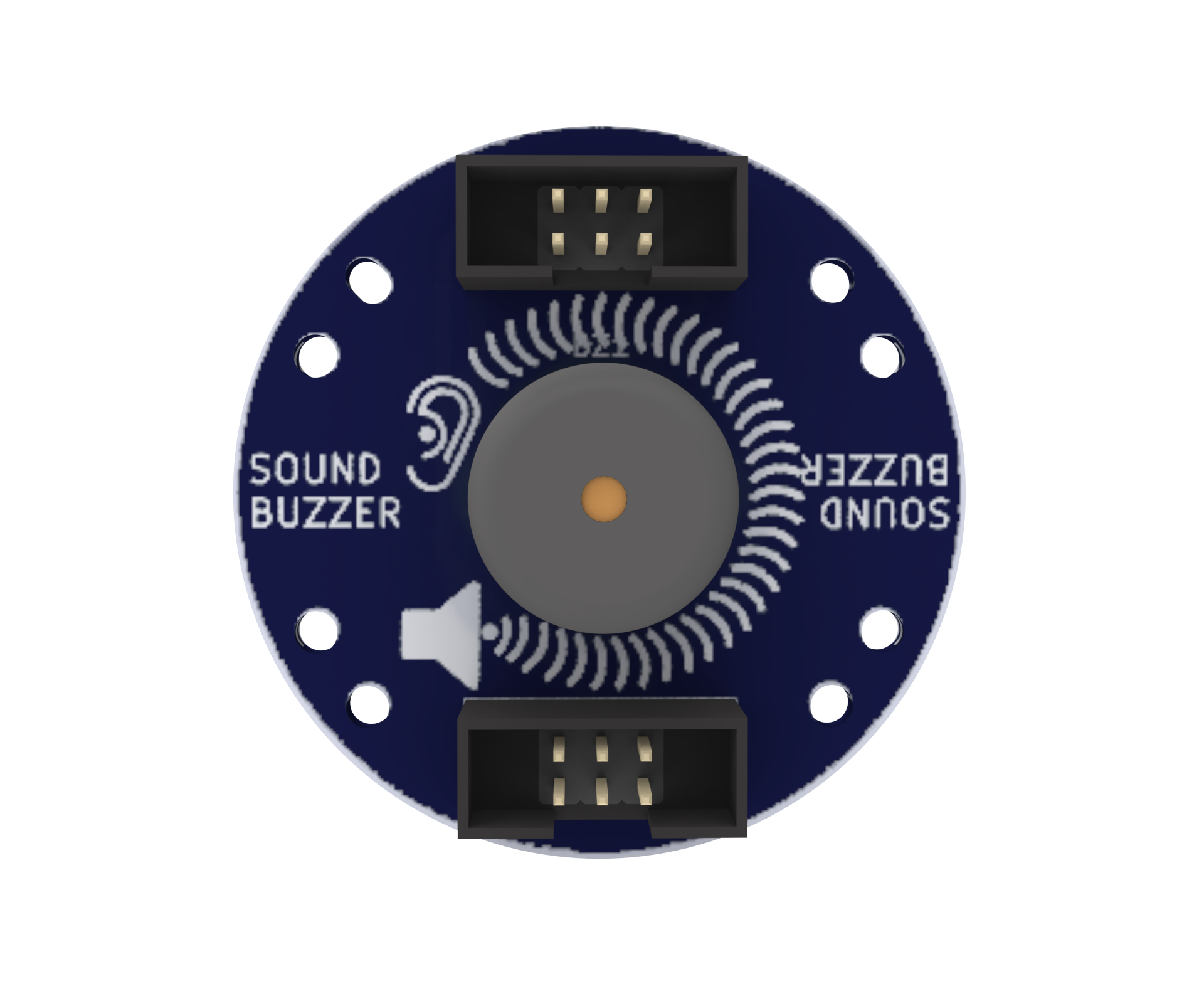
Sound Buzzer: An component that produces an audible sound and can be utilised by the user to produce an audible output at any of the program’s defined frequencies.
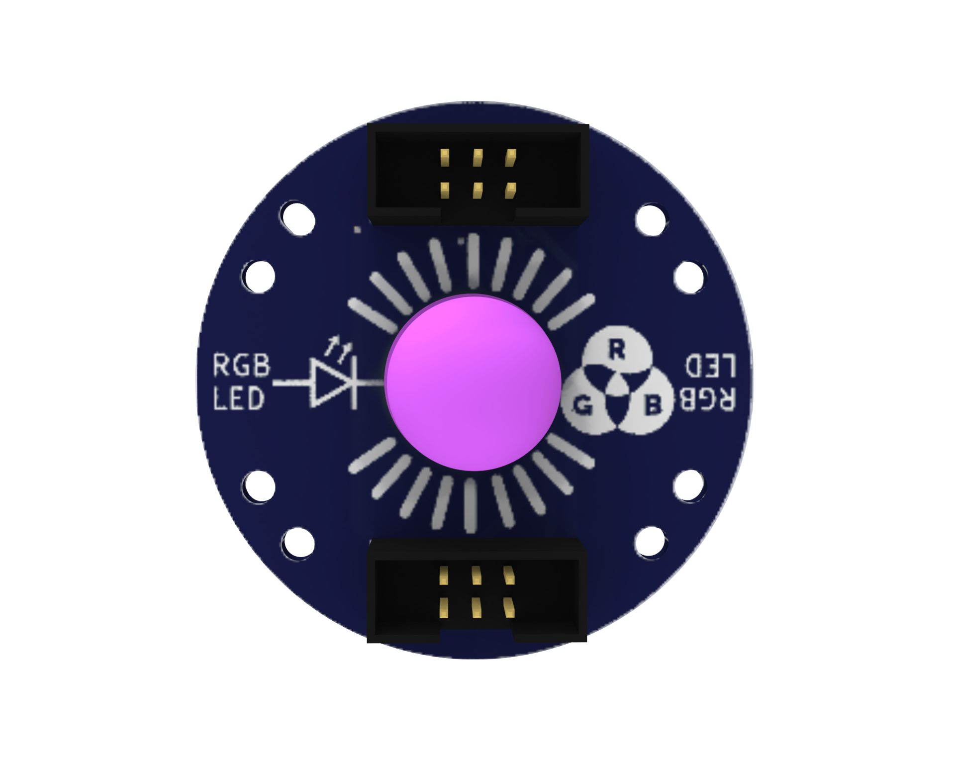
RGB LED: An RGB LED is an LED (Light Emitting Diode) that can be used to give users visual feedback by emitting various combinations of the colours red, green, and blue.
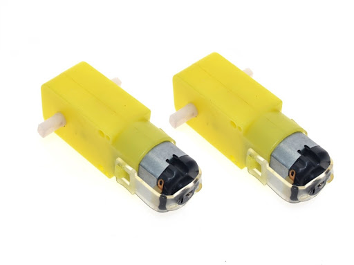
Battery-operated (BO) motors: These are DC (direct current) motors that have a gearbox attached to them, allowing them to operate at lower speeds and with more torque. In robotics and other electrical tasks, they are frequently employed.
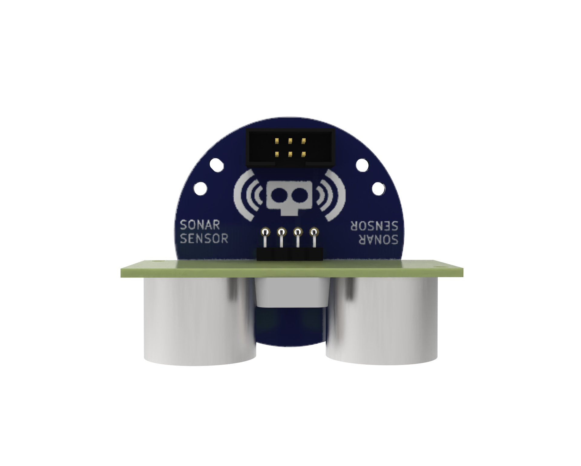
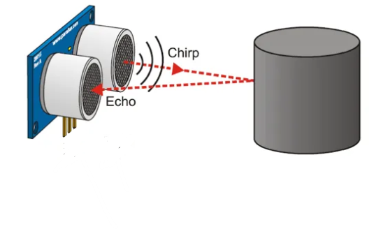
Sonar Sensor: A sonar sensor is a device that measures distances using ultrasonic waves. It operates by emitted a sound wave and listening for the echo that returns after striking an object. The sensor can calculate how far away an object is by measuring how long it takes for the echo to return. Robots frequently employ sonar sensors to aid in navigation and avoid obstructions. They function effectively both inside and outside and are comparatively simple to operate. They may not always be as accurate as other sensors and are susceptible to influences like wind, humidity, and temperature.
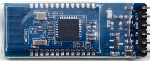
Bluetooth: A wireless communication module that enables the robot to communicate with other devices, such as smartphones.
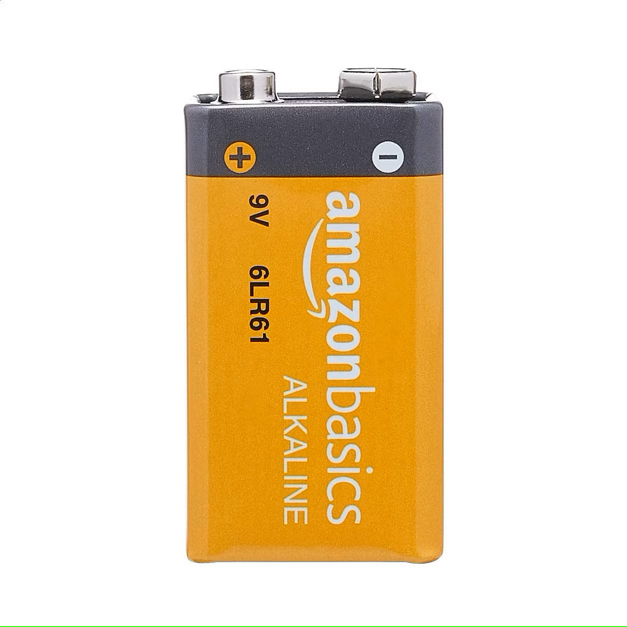
9V Battery: A common battery used in electronic projects, which provides 9 Volts of power for motor driving.
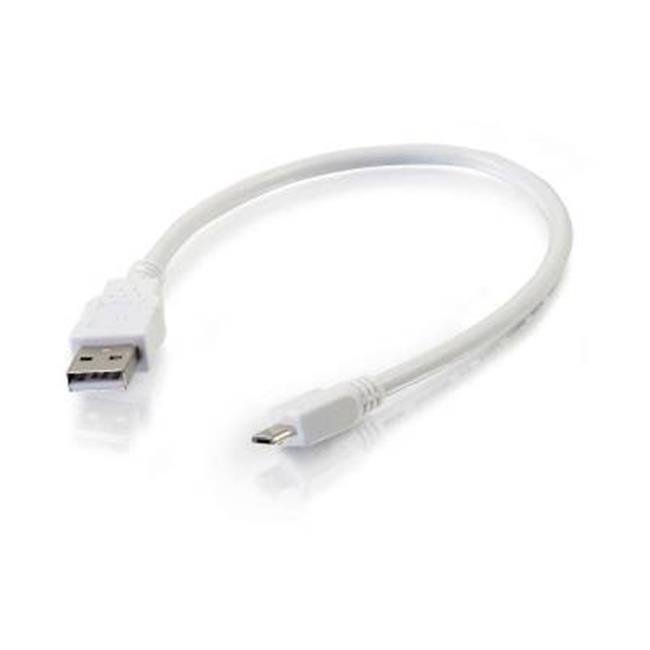
Micro USB Cable: A cable used to connect the CPU to a computer for programming or to power the CPU with a power bank.
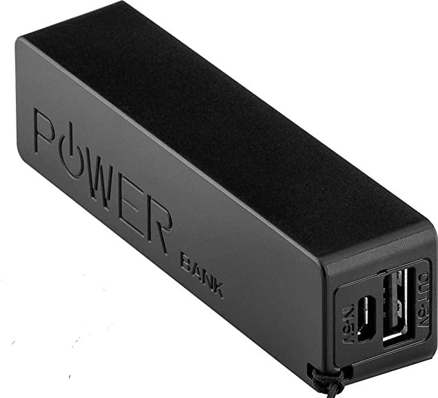
Power Bank: A portable battery pack is used to power the robot.
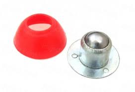
Caster Wheel: A wheel that supports the front of the robot and allows it to turn easily.
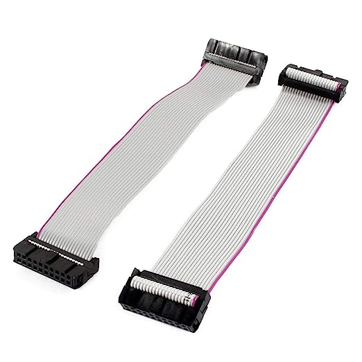
Snap Wires: Wires with pre-attached connectors that can be easily snapped on and off the components, making it easy to connect and disconnect components.
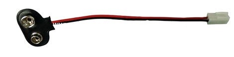
Battery to Snap Connector: A connector that allows the 9V battery to be easily connected to the motor driver.
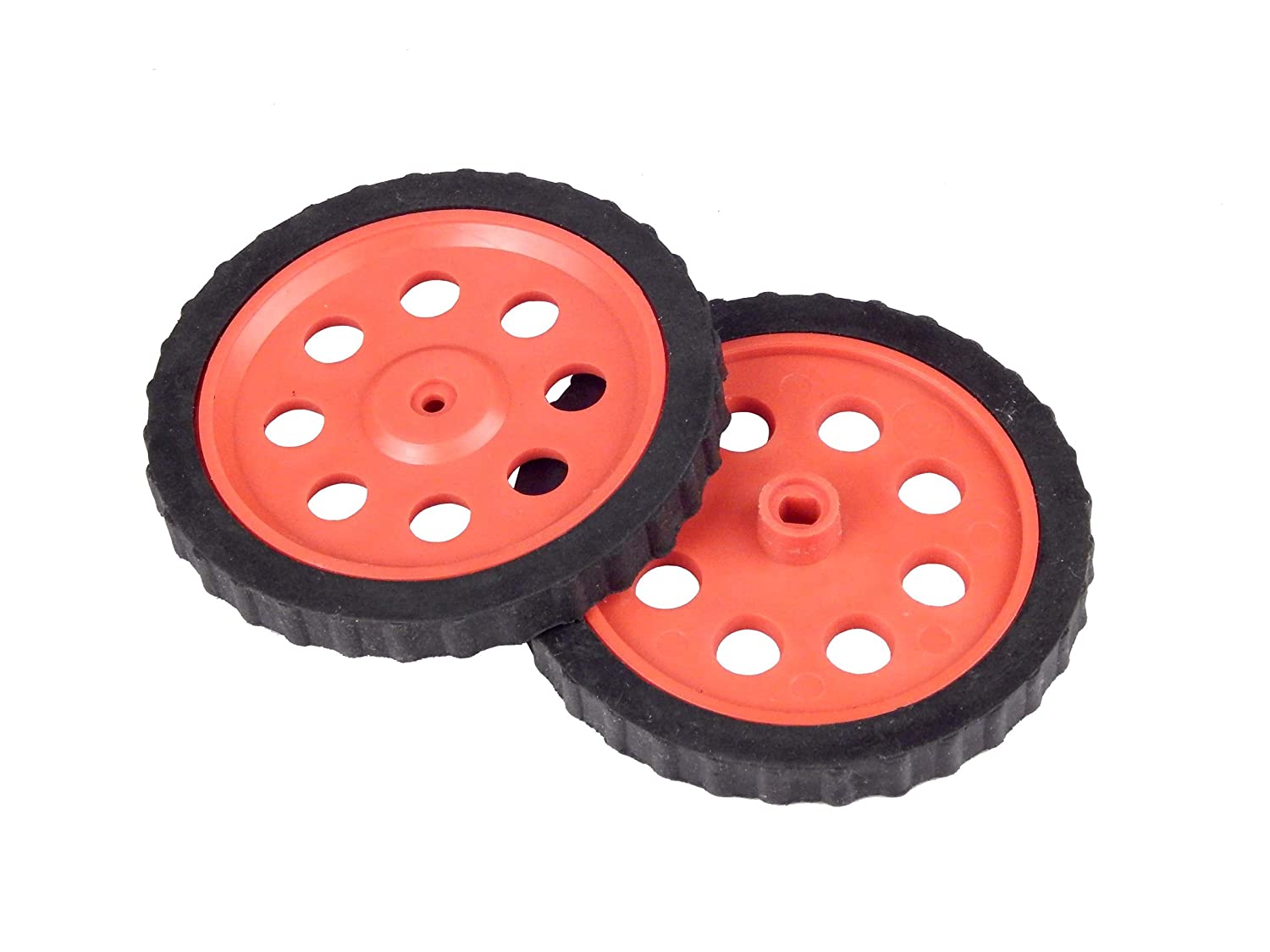
Wheels: Two wheels that drive the robot forward and backward.
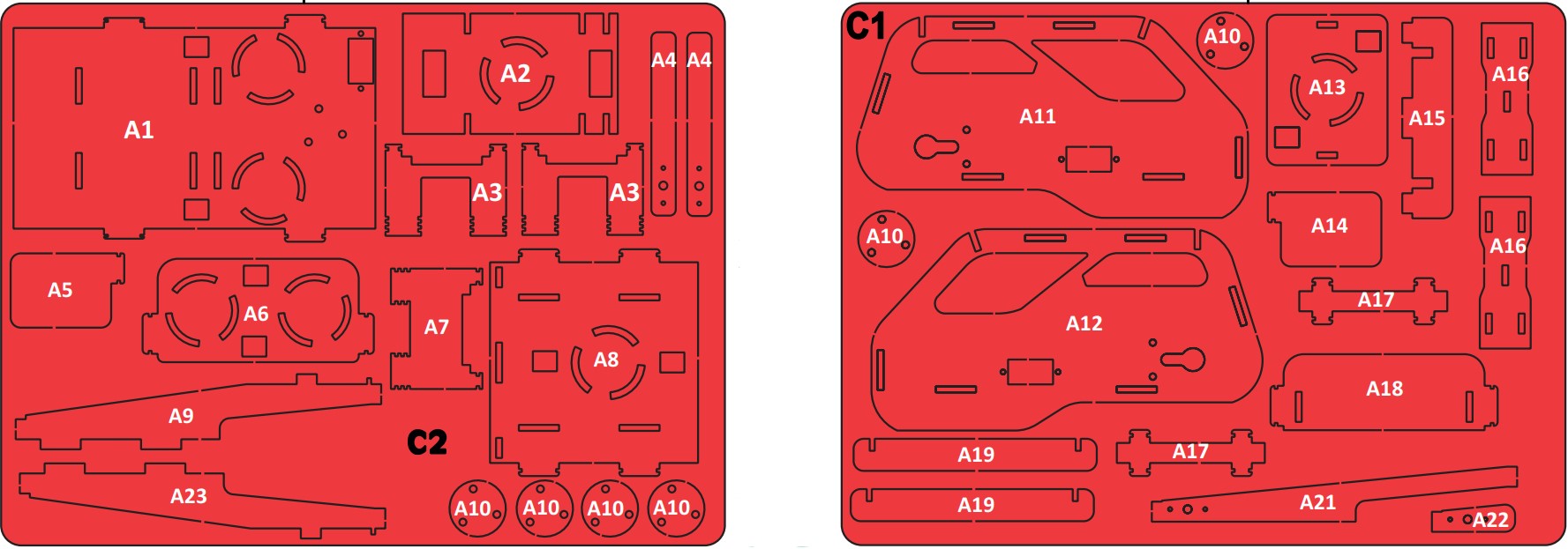
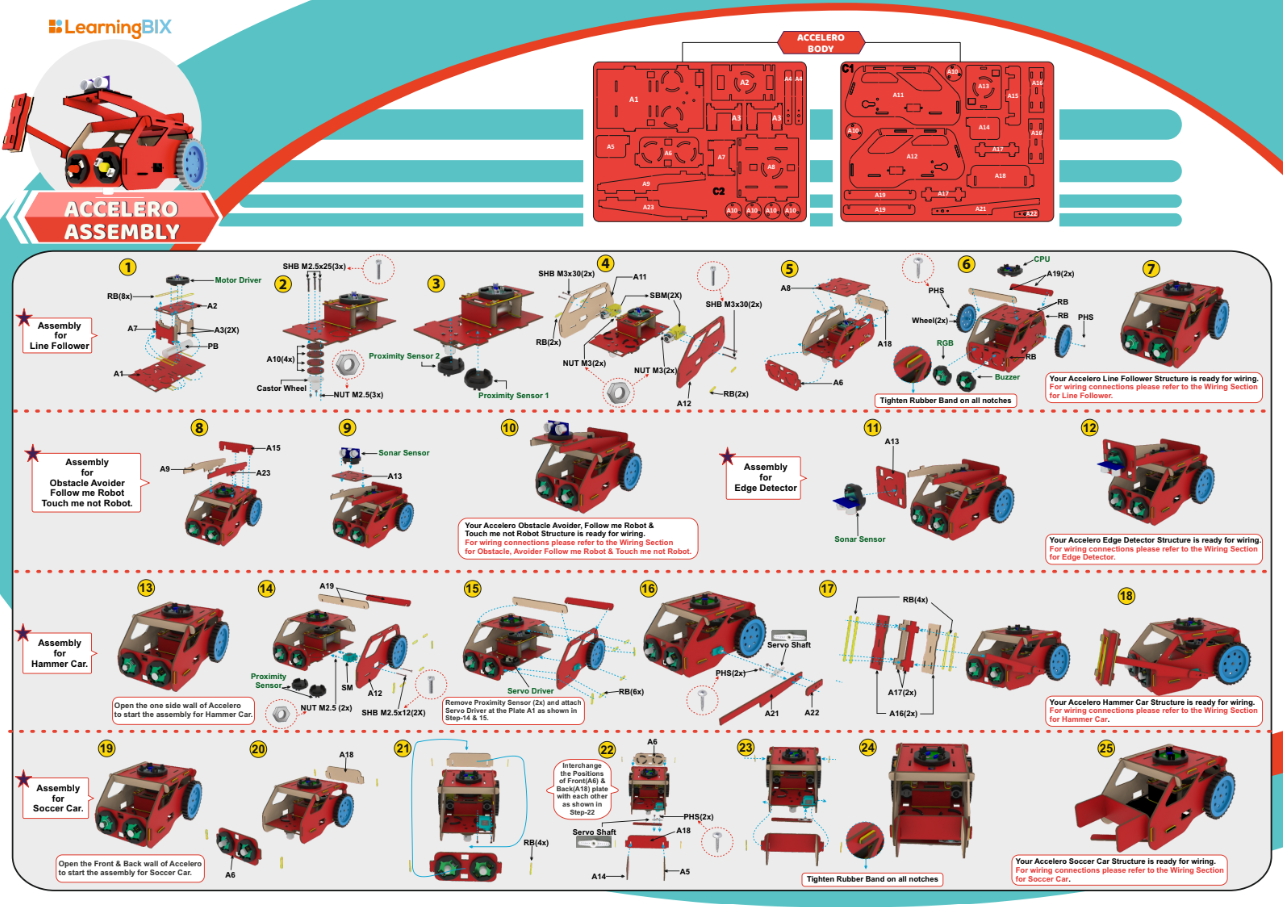
Accelero Body Sheet (C1 and C2): A sheet of MDF material that is used to create the body of the robot.
Rubber Bands: Rubber bands are used to attach the body parts to each other.

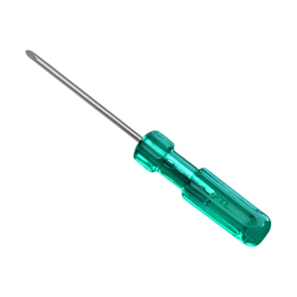
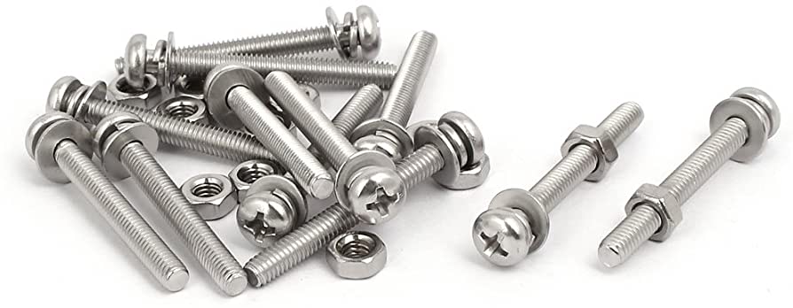
Screwdriver and Screw Fasteners: Used to attach components to the body of the robot.
Building the Chassis
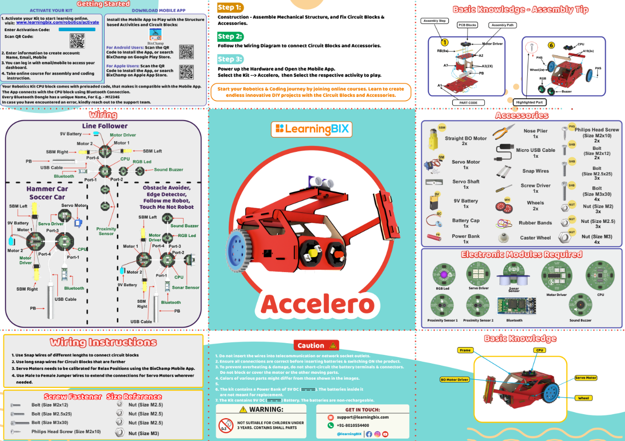
The first step is to build the chassis of the robot car using the MDF sheet. Rubber bands will provide a flexible and adjustable solution for holding parts together. Use the caster wheel at the front of the chassis and mount the two BO motors on the back two wheels. Mount all the electronics in their place.
Wiring the Circuit
- According to the diagram please connect all the wires.
- Use snap wires of different lengths to connect circuit blocks.
- Use long snap wires for circuit blocks that are farther apart.
Download Arduino IDE
You can take the following actions to download the Arduino IDE::
- Go to the official Arduino website at: www.arduino.cc
- Click on the “Software” menu item in the top navigation bar.
- Select the “Downloads” option from the drop-down menu.
- Scroll down to find the section for the Arduino IDE and select the appropriate version for your operating system (Windows, Mac, or Linux).
- Click on the download link for the selected version to start the download.
- Once the download is complete, run the installation file and follow the instructions to install the Arduino IDE on your computer.
Following installation, you may launch the Arduino IDE and begin CPU programming.
Writing the Code
The methodology behind the sonar sensor, CPU, and motor driver code for an obstacle avoiding car is explained as follows:
Define the Pins: The pins for the motor driver, motors, and sonar sensor must be defined first. This enables proper communication between the code and the hardware parts.
Install the code: The pins are configured as inputs or outputs as necessary in the void setup () function. As an illustration, the sonar echo pin is configured as an input to receive the signal and the sonar trigger pin is set as an output to deliver the signal.
Sonar data reading: The sonar sensor is used to calculate the distance to any obstacles in front of the car in the void loop () function. To do this, a signal is sent from the trigger pin, and the time it takes for the signal to return to the echo pin is timed.
Determine the Movement of the Car: If a barrier is present, the code instructs the driver to turn the automobile in that direction. If there is no obstruction, the code employs the motor driver to advance the vehicle. Which side of the obstruction is closest, as determined by the sonar sensor, determines whether to turn left or right.
Use of Motor Control Functions: Motor control functions are used to steer the car’s motors in the direction you want it to go. For instance, the move_forward () function instructs both motors to move forward, whereas the turn_left () function instructs the left motor to stop while the right motor advances, turning the vehicle to the left.
Test and Improve the Code: The performance of the car is evaluated after the code has been uploaded to the microcontroller. It is possible to increase the performance of the car by making changes to the code if it is not avoiding obstacles as required.
In general, the logic of the code for an obstacle-avoiding automobile relies on employing a sensor to identify impediments and a motor driver to move the vehicle in the required direction to avoid those obstacles.
Obstacle Avoiding Robot Code
Uploading Code
After downloading the .ino file to your computer, you need to open it in the Arduino IDE and upload it to the CPU. Here are the steps to do so:
- Open the Arduino IDE software on your computer.
- Connect your CPU to the computer using a USB cable.
- In the Arduino IDE, click on “File” and then “Open“.
- Browse and select the .ino file that you downloaded.
- The code will open in a new window in the Arduino IDE.
- Before uploading the code to the CPU, make sure that the correct board type and serial port are selected from the “Tools” menu.
- To upload the code, click on the “Upload” button (right-pointing arrow) in the Arduino IDE toolbar. The IDE will compile the code, and if there are no errors, it will upload the code to the CPU.
- After uploading the code, the Arduino board will start running the program automatically.
Note: During the upload process, you may see some messages in the bottom section of the Arduino IDE. If the upload is successful, you will see a “Done uploading” message.
In summary, after downloading the .ino file, you need to open it in the Arduino IDE, select the correct board type and serial port, and then upload the code to the CPU. Once the upload is successful, the code will start running on the CPU.
Testing the Robot Car
- Power on the CPU using the power bank power source.
- Make sure the motor driver is connected to the CPU and the motors are connected to the motor driver.
- A 9-volt battery must be connected to the motor driver battery pin.
- Download the Bixchamp2.0 app
- Connect to the mobile app: Pair your mobile device with the Bluetooth module on the car.
- Open the mobile app and connect to the car.
- Use the app to start the car and put it in motion.
- As the car moves, it should use the sonar sensor to detect obstacles and adjust its path to avoid collisions. Use the app to monitor the sensor data and make sure the car is detecting obstacles correctly.
- Try different scenarios to test the car’s obstacle avoiding abilities, such as placing obstacles in its path or changing the speed and direction of the car.
Conclusion
An obstacle avoiding car is a great example of how modern technology can be used to create innovative and practical solutions to everyday problems. By using a sonar sensor to detect obstacles and a CPU to process the sensor data, the car can navigate its environment and avoid collisions. The use of a motor driver and power supply allows for precise control of the car’s movement. With the right components and programming, it’s possible to create a sophisticated obstacle avoiding car that can operate autonomously or be controlled remotely. Whether you’re a hobbyist, student, or professional, building an obstacle avoiding car is a fun and rewarding project that can help you develop your skills in electronics, programming, and robotics.
