

In recent years, line follower robot cars have gained popularity, especially among beginners and hobbyists. They are easy to construct and offer fantastic opportunities to learn about sensors, controls, and robotics. In this post, we’ll demonstrate how to construct a line-following robot car that can drive along a black line using two IR proximity sensors.
Materials Needed
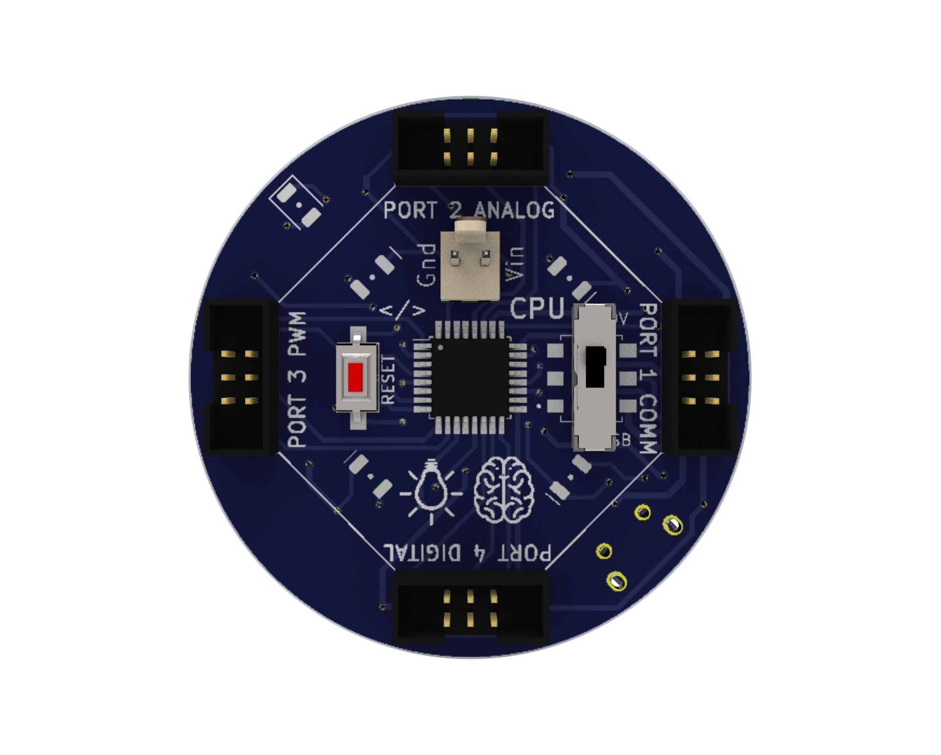
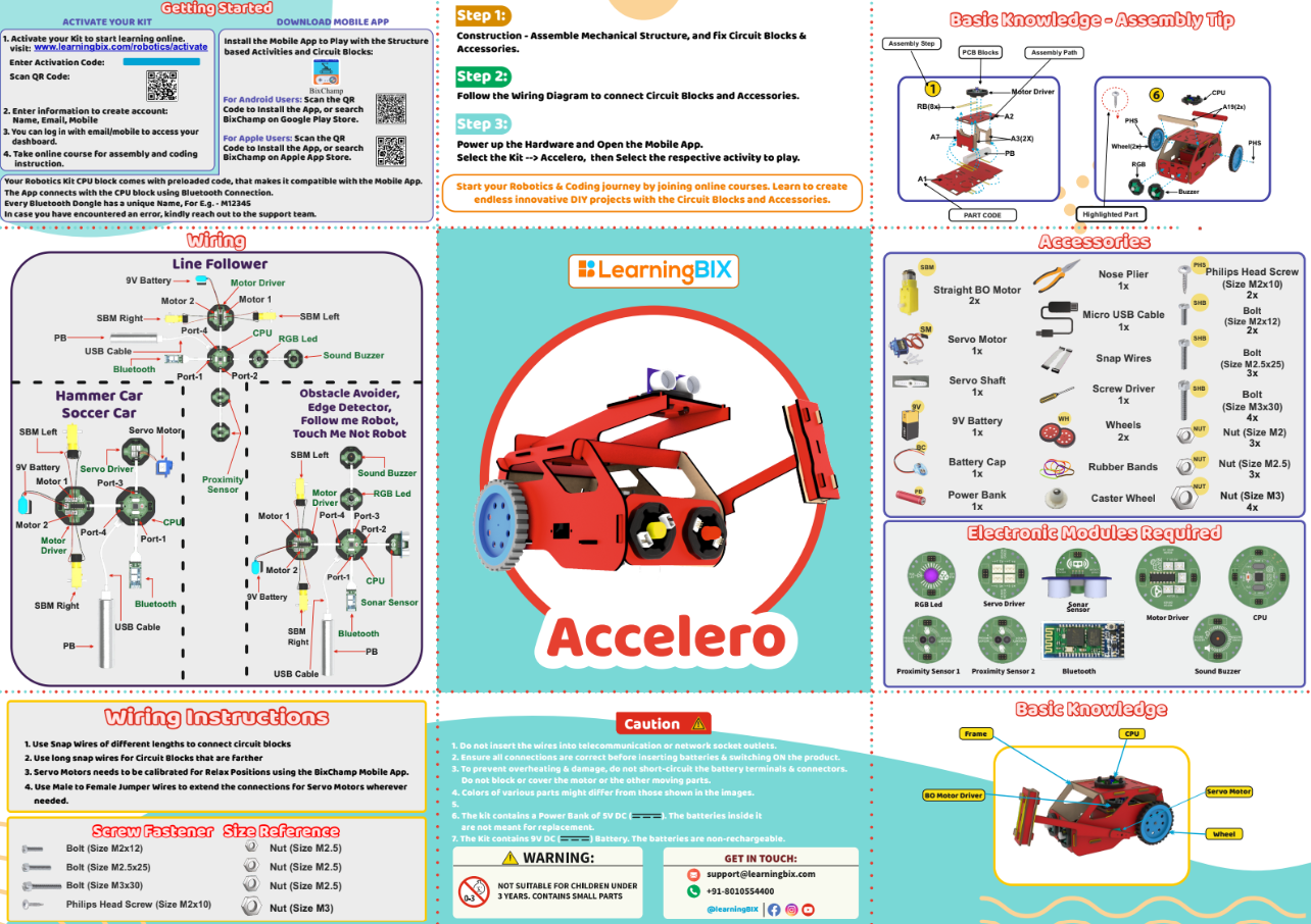
CPU: A microprocessor board used as the robot’s brain that may be programmed or Bluetooth-controlled to do a variety of tasks. We have four ports on this board, and they are each used for various input and output tasks by connecting to various electronic parts.
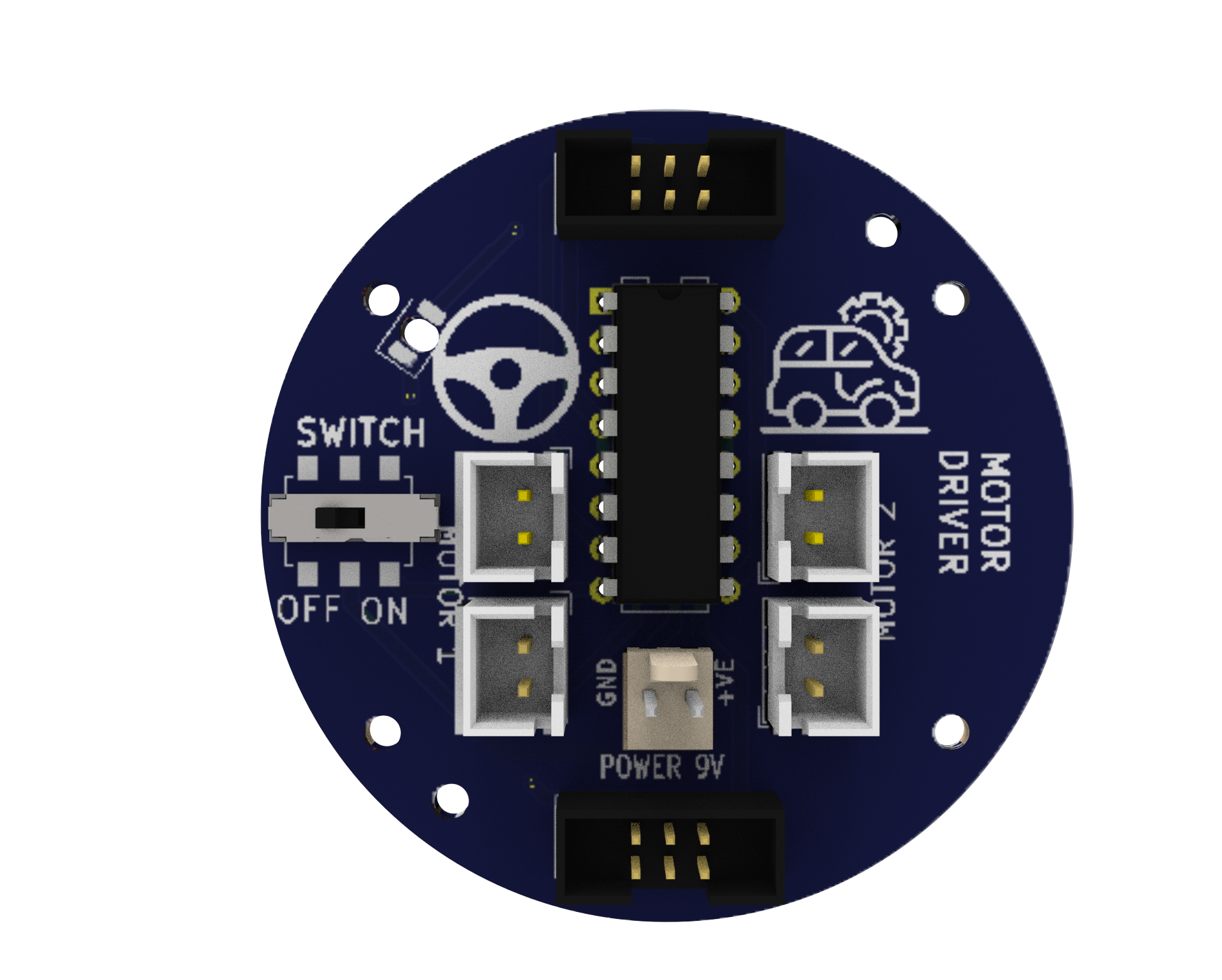
Motor Driver: A circuit that enables the robot to regulate the motors’ speed and direction. It uses a separate 9V battery to supply the motors with the necessary power and voltage.
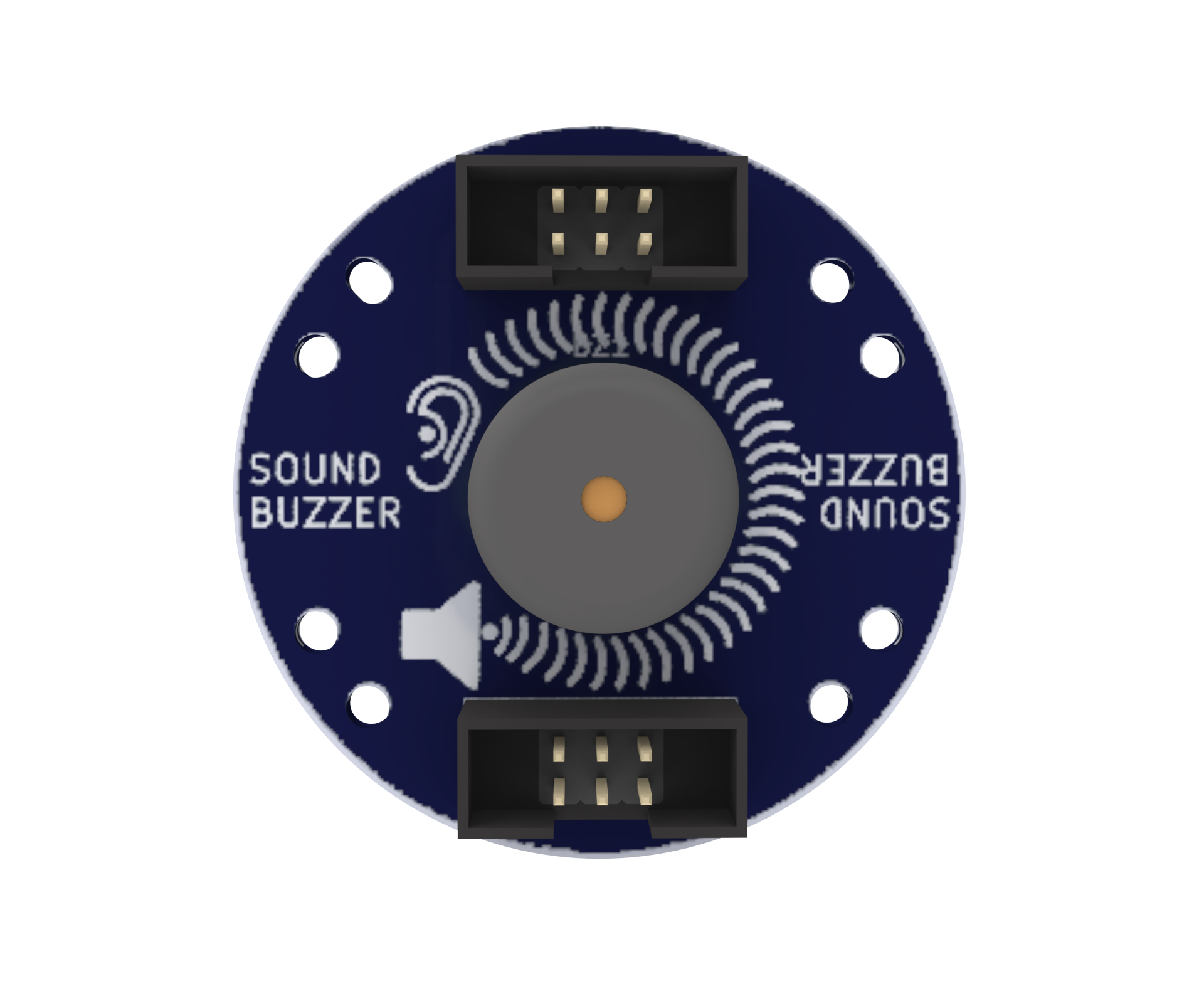
Sound Buzzer: An component that produces an audible sound and can be utilised by the user to produce an audible output at any of the program’s defined frequencies.
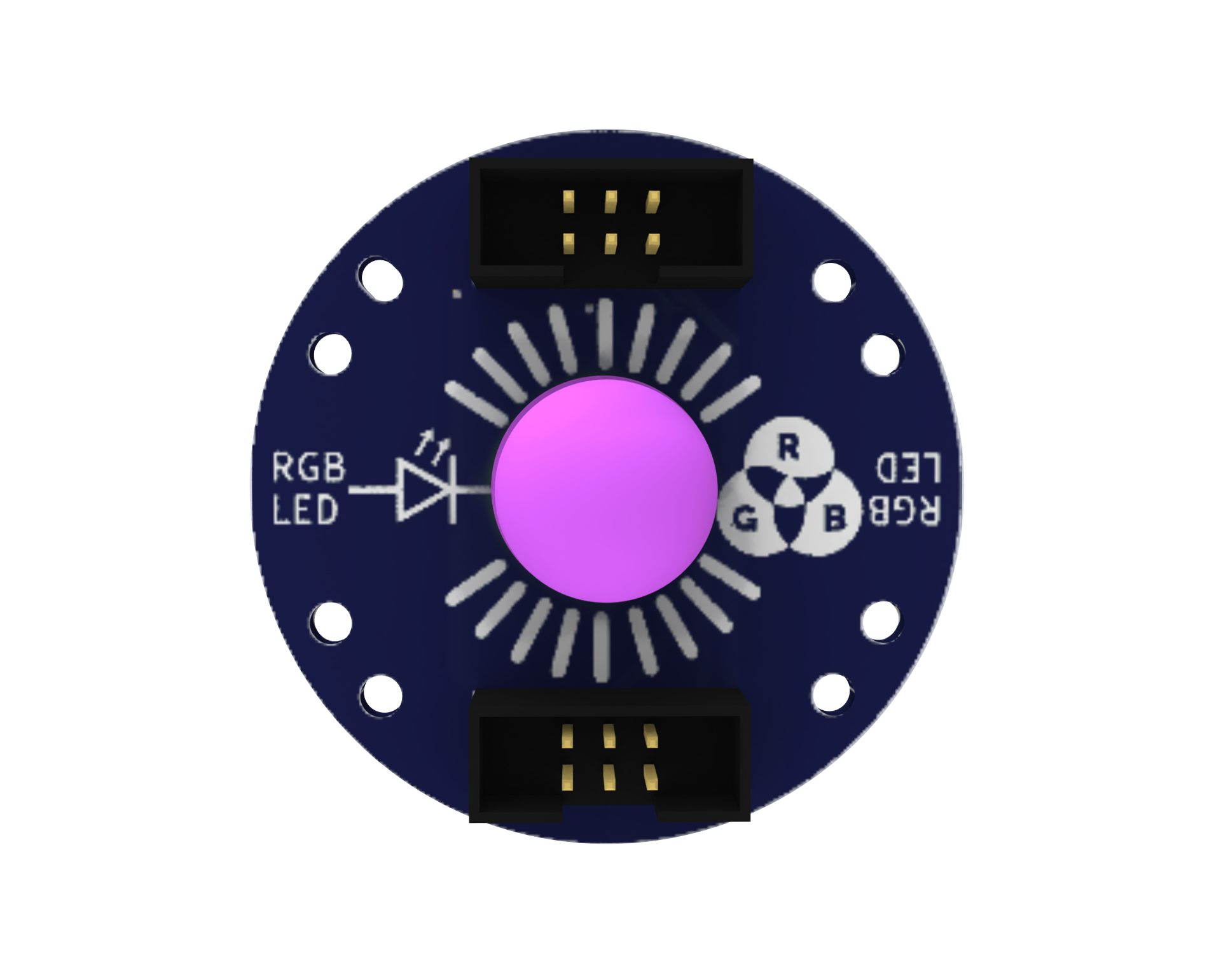
RGB LED: An RGB LED is an LED (Light Emitting Diode) that can be used to give users visual feedback by emitting various combinations of the colours red, green, and blue.
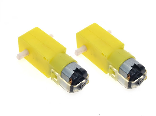
Battery-operated (BO) motors: These are DC (direct current) motors that have a gearbox attached to them, allowing them to operate at lower speeds and with more torque. In robotics and other electrical tasks, they are frequently employed.
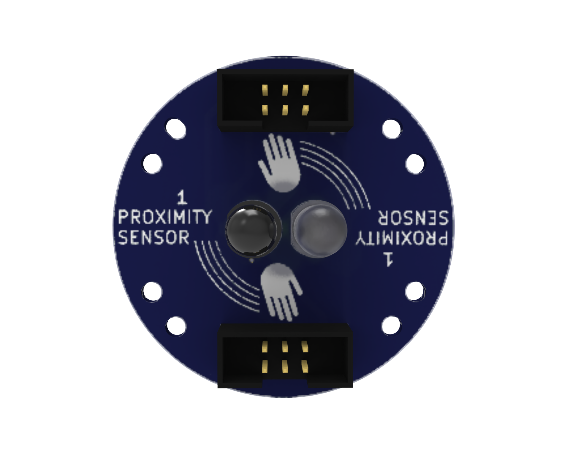
Proximity Sensors: An IR analog proximity sensor is a type of sensor that detects the presence of an object by emitting and measuring infrared light. It provides a continuous output signal, allowing for precise control of the system. It can be used in various applications, including robotics and industrial automation.
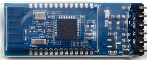
Bluetooth: A wireless communication module that enables the robot to communicate with other devices, such as smartphones.
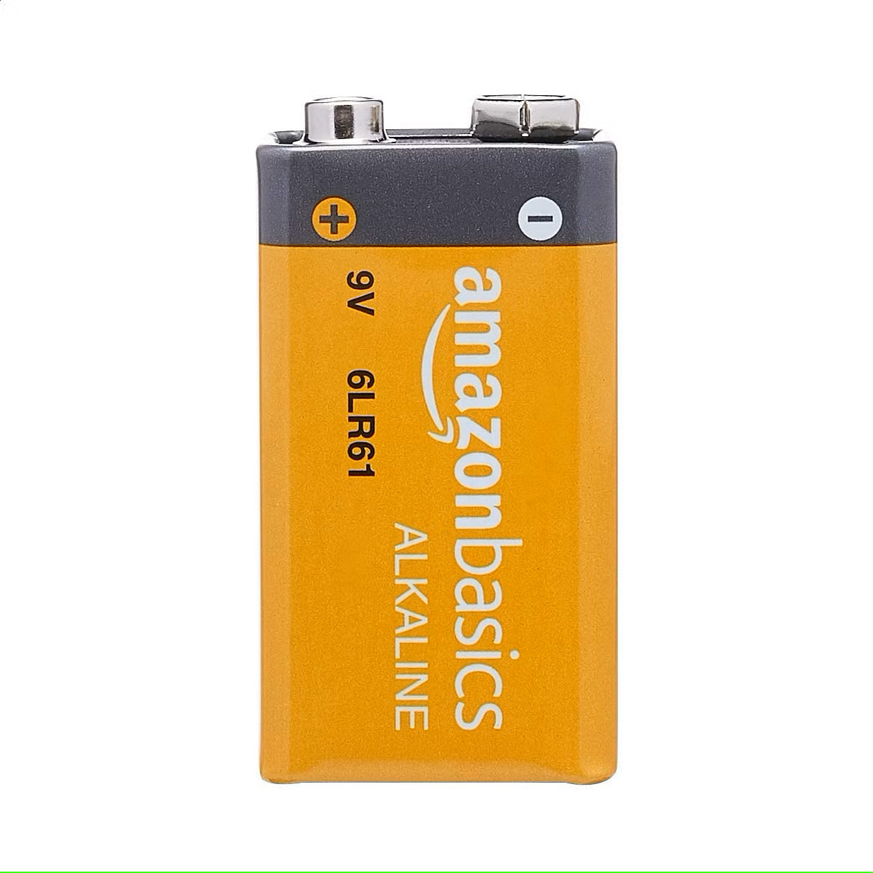
9V Battery: A common battery used in electronic projects, which provides 9 Volts of power for motor driving.
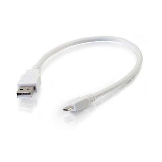
Micro USB Cable: A cable used to connect the CPU to a computer for programming or to power the CPU with a power bank.
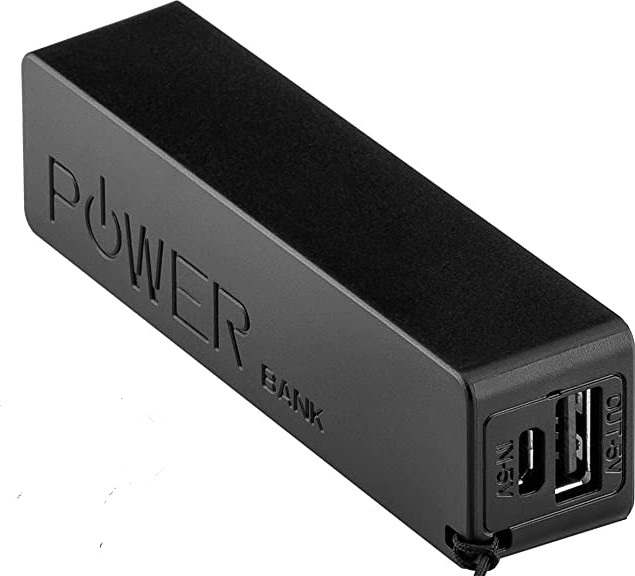
Power Bank: A portable battery pack is used to power the robot.
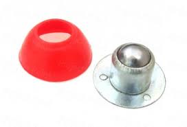
Caster Wheel: A wheel that supports the front of the robot and allows it to turn easily.
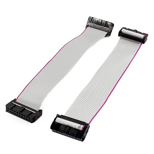
Snap Wires: Wires with pre-attached connectors that can be easily snapped on and off the components, making it easy to connect and disconnect components.
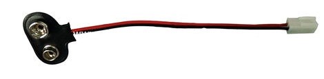
Battery to Snap Connector: A connector that allows the 9V battery to be easily connected to the motor driver.
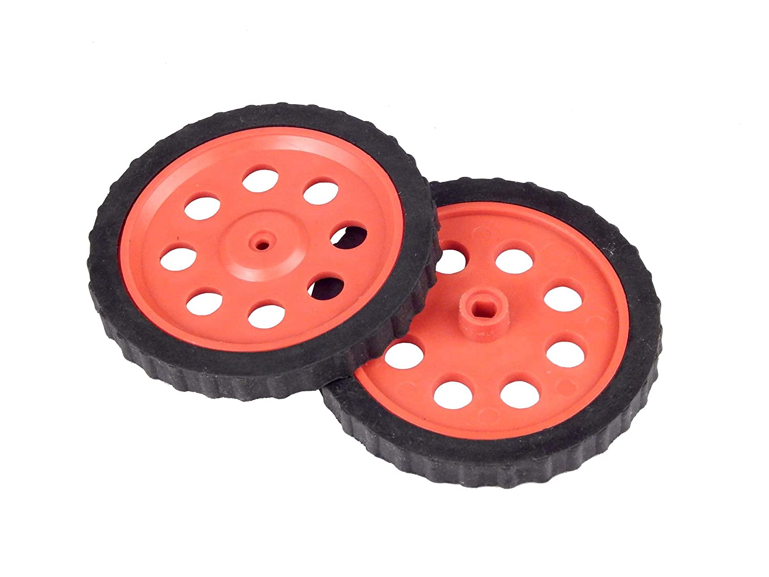
Wheels: Two wheels that drive the robot forward and backward.
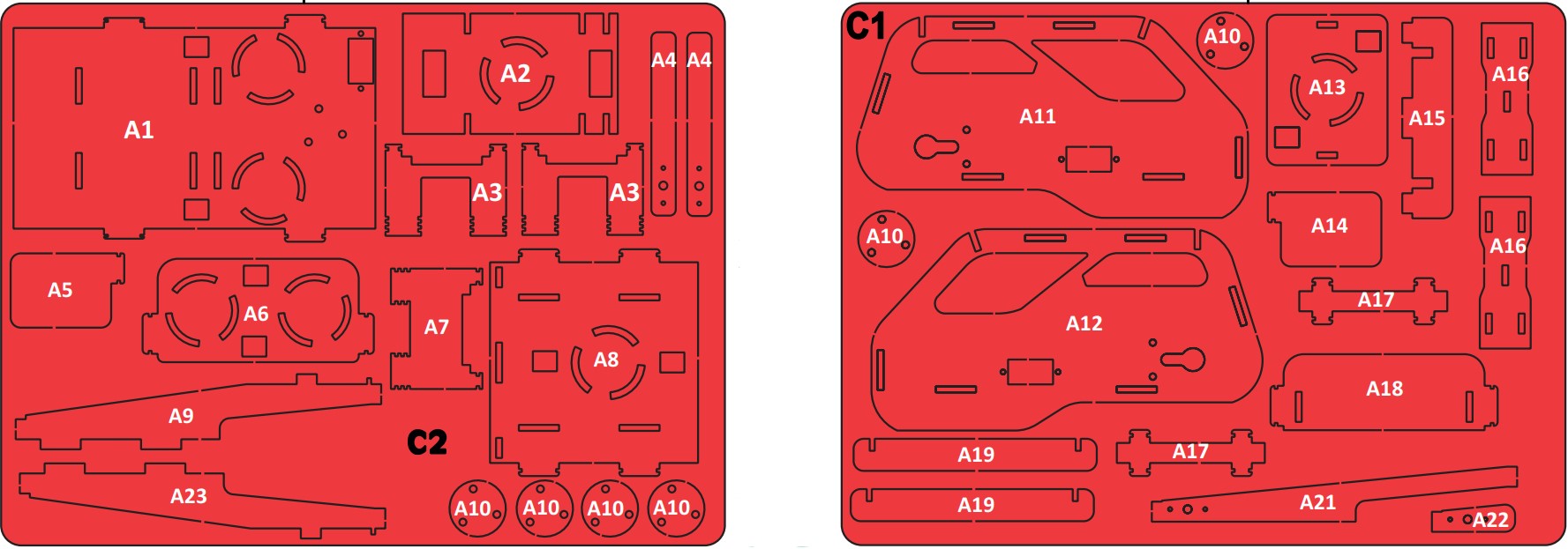
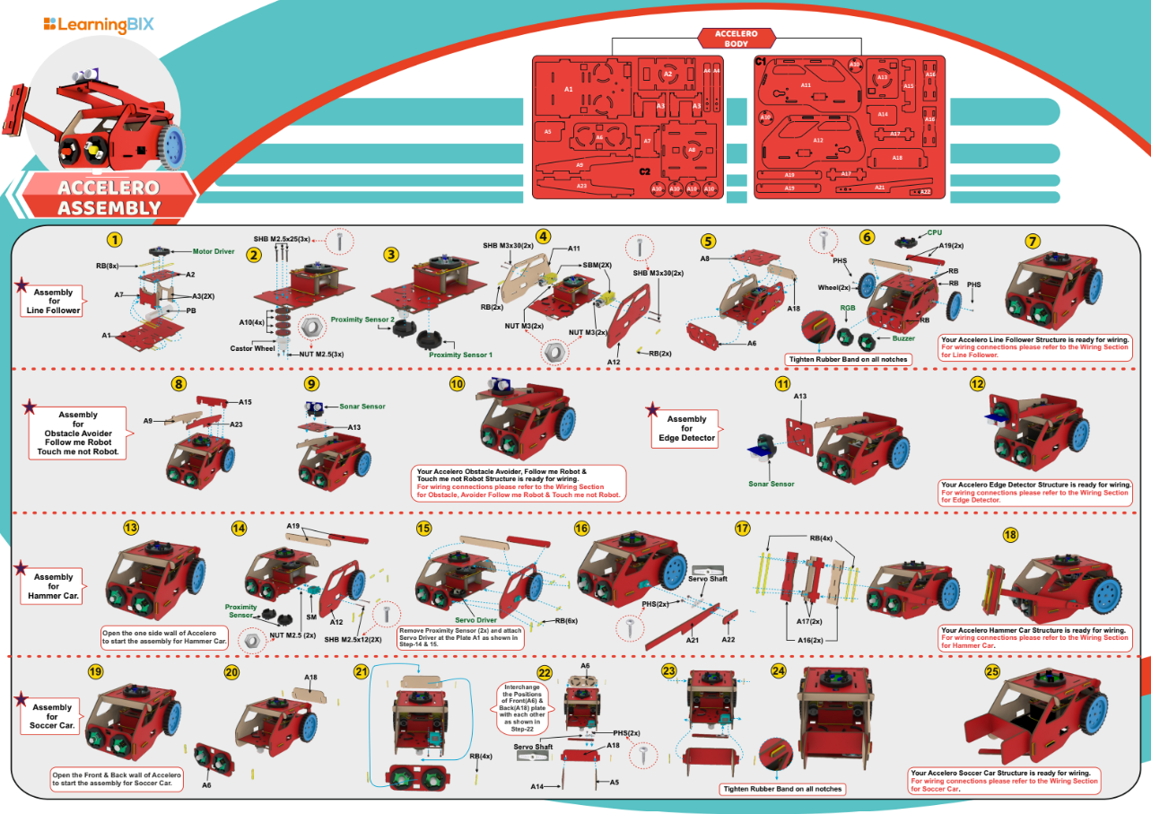
Accelero Body Sheet (C1 and C2): A sheet of MDF material that is used to create the body of the robot.
Rubber Bands: Rubber bands are used to attach the body parts to each other.

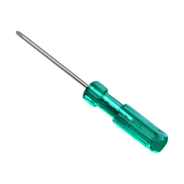
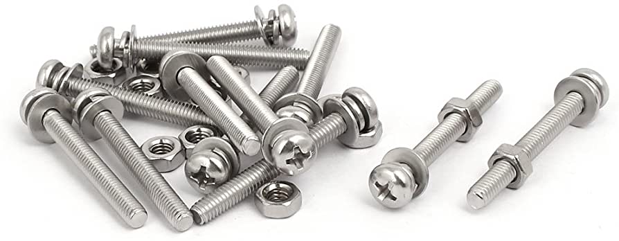
Screwdriver and Screw Fasteners: Used to attach components to the body of the robot.
Building the Chassis
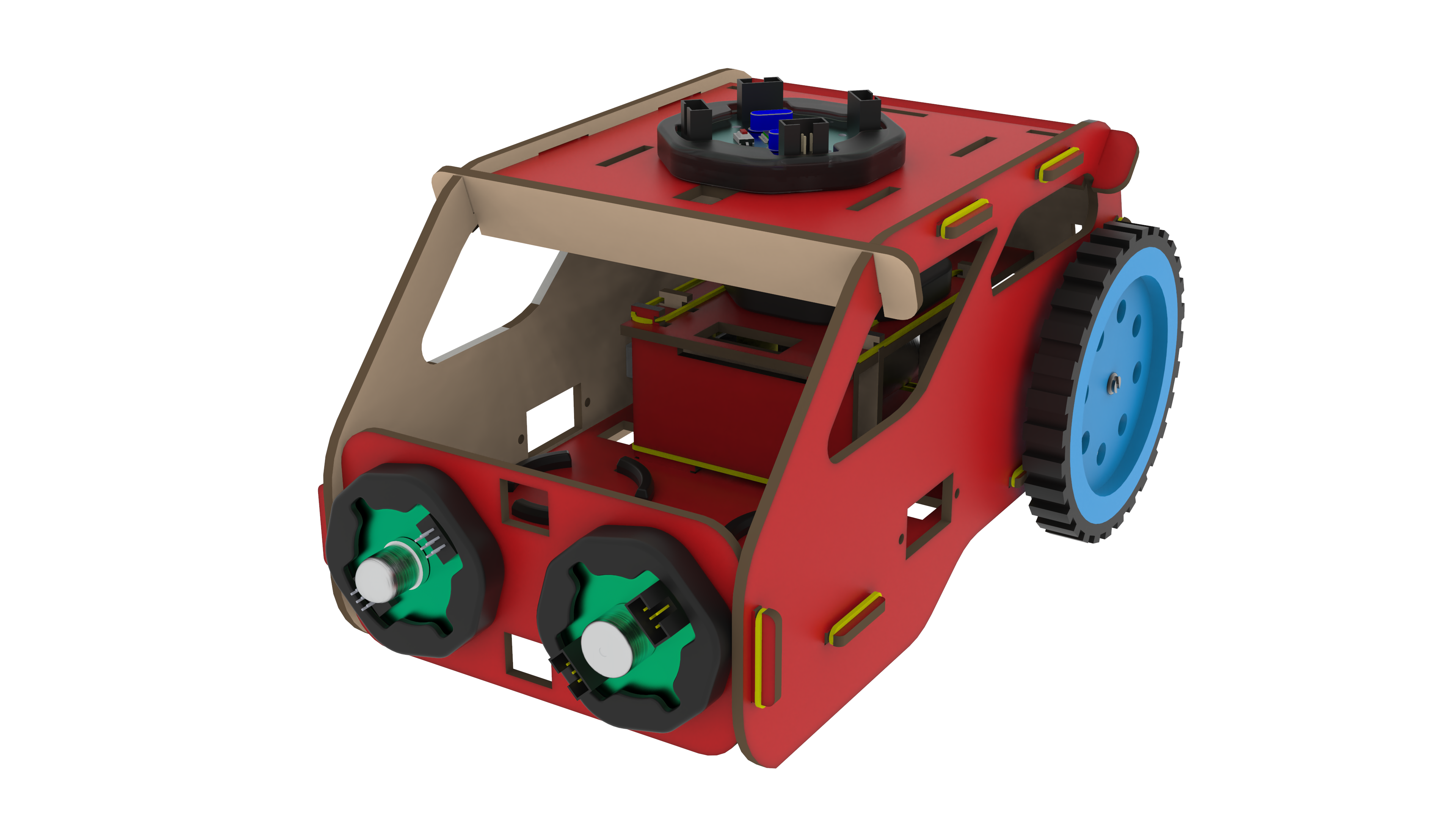
The robot car’s chassis should initially be constructed using the MDF sheet. Rubber bands can offer a versatile and customizable way to assemble pieces. Use the caster wheel at the front of the chassis and mount the two BO motors on the back two wheels. Mount all the electronics at their place.
Wiring the Circuit
- According to the diagram please connect all the wires.
- Use snap wires of different lengths to connect circuit blocks.
- Use long snap wires for circuit blocks that are farther apart.
Download Arduino IDE
You can take the following actions to download the Arduino IDE:
- Go to the official Arduino website at: www.arduino.cc
- Click on the “Software” menu item in the top navigation bar.
- Select the “Downloads” option from the drop-down menu.
- Scroll down to find the section for the Arduino IDE and select the appropriate version for your operating system (Windows, Mac, or Linux).
- Click on the download link for the selected version to start the download.
- Once the download is complete, run the installation file and follow the instructions to install the Arduino IDE on your computer.
You can launch the Arduino IDE and begin configuring your Arduino board after installation.
Writing the Code for Line Follower
The methodology behind the code for a line-following robot that uses two IR sensors, Bluetooth, and a smartphone app is described as follows:
Define the Pins: The two IR sensors and the Bluetooth module’s pins must be defined first. This enables effective communication between the code and the sensor and the module.
Setup the code: The pins are configured as inputs or outputs as necessary in the void setup() method. For instance, the Bluetooth module pins are configured to receive data from the mobile app, and the two IR sensor pins are set up as inputs to receive signals from the sensors.
Read the sensors data: The two IR sensors are utilised in the void loop() method to determine if the robot is on the line or off it. Depending on whether it is over the line or not, each sensor determines.
Receive Instructions From the Mobile App: A smartphone app that transmits instructions to the robot’s Bluetooth module can be used to control the machine remotely. The loop() function in the code keeps an eye out for these commands and reacts appropriately. For example, if the mobile app instructs the robot to advance forward, the code causes the motors to start moving.
Determine the Robot’s Movement: If both sensors are outside of the marked area and the mobile app doesn’t provide a command, the robot travels onward. If only one sensor crosses the line and no order is given, the robot moves in the direction of the crossing sensor. The robot stops if neither sensor crosses the line and no order is given.
Use of Motor Control Functions: The robot’s movement is managed via helper functions. For instance, the move_forward() method instructs the robot to move forward while the turn_left() function instructs the robot to turn left while stopping the left motor and moving the right motor.
Test and Refine the Code: The robot’s performance is evaluated after the code has been uploaded to the microcontroller. Changes to the code can be performed to enhance the robot’s performance if it is not moving in the desired direction or reacting to orders as intended.
In general, the code for a line-following robot that uses two IR sensors, Bluetooth, and a mobile app is built around the idea of using the sensors to determine whether the robot is on the line or not and then using that information to regulate its movement. Also, a mobile app that communicates commands to the robot’s Bluetooth module enables the remote operation of the machine. The user can remotely control the robot’s movement since the algorithm listens to these commands and acts accordingly.
Line Follower Robot Code
Uploading Code
After downloading the .ino file to your computer, you need to open it in the Arduino IDE and upload it to the CPU. Here are the steps to do so:
- Open the Arduino IDE software on your computer.
- Connect your CPU to the computer using a USB cable.
- In the Arduino IDE, click on “File” and then “Open“.
- Browse and select the .ino file that you downloaded.
- The code will open in a new window in the Arduino IDE.
- Before uploading the code to the CPU, make sure that the correct board type and serial port are selected from the “Tools” menu.
- To upload the code, click on the “Upload” button (right-pointing arrow) in the Arduino IDE toolbar. The IDE will compile the code, and if there are no errors, it will upload the code to the CPU.
- After uploading the code, the Arduino board will start running the program automatically.
Note: During the upload process, you may see some messages in the bottom section of the Arduino IDE. If the upload is successful, you will see a “Done uploading” message.
In summary, after downloading the .ino file, you need to open it in the Arduino IDE, select the correct board type and serial port, and then upload the code to the CPU. Once the upload is successful, the code will start running on the CPU.
Testing the Line Follower Robot Car
- Upload the line follower code to the CPU.
- Power on the CPU using the power bank power source.
- Place the robot on a surface with a black line drawn on it.
- Make sure the motor driver is connected to the CPU and the motors are connected to the motor driver.
- A 9-volt battery must be connected to the motor driver battery pin.
- Place proximity sensor 1 on the black line and white surface, and note the values at both locations. Do the same thing for proximity sensor 2.
- Set the value of both sensors in the Bixchamp2.0 app.
- Observe if the robot is moving according to the line or not. If not, adjust the IR proximity sensors and motors accordingly.
- To fine-tune the robot’s performance, if necessary, change the values in the app.
Conclusion
Building a line-following robot car with two IR proximity sensors is a fun and educational project that anyone can do. By following the steps outlined in this article, you can build your own robot car that can follow a black line. With a little creativity and experimentation, you can also modify the design to build different models of the accelero kit. So, get started today and see what you can create!
